Use this information to remove and replace the system-board assembly.
- This procedure should be performed only by trained service technicians.
- If possible, back up all compute node settings, including the settings for any options installed in the compute node. You can backup and restore system settings using the Advanced Setup Utility (ASU) (see Advanced Settings Utility (ASU) for Lenovo x86 servers website for information and instructions).
- Read Safety and Installation guidelines.
- If the compute node is installed in a chassis, remove it (see Removing a compute node from a chassis for instructions).
- Carefully lay the replacement system-board assembly (system board FRU) and the defective system-board assembly (defective node) side-by-side on a flat, static-protective surface.
- Obtain the following for use during the replacement procedure
(see Parts listing, Types 9532 and 2951).
See System-board layouts for more information about the locations of the connectors, switches, and LEDs on the system board.
To remove and replace the system-board assembly, complete the following steps:
-
Transfer microprocessor 1 (rear microprocessor)
and its heat sink from the defective system-board assembly to the
replacement system-board assembly. Use the microprocessor installation
tool that comes with the replacement system-board assembly to remove
the microprocessor from the defective system-board assembly and install
it immediately in the replacement system-board assembly.
-
Open the microprocessor socket release levers and retainer
on the defective system-board assembly.
Attention: Do not use any tools or sharp objects to lift the release levers on the microprocessor socket. Doing so might result in permanent damage to the system board.
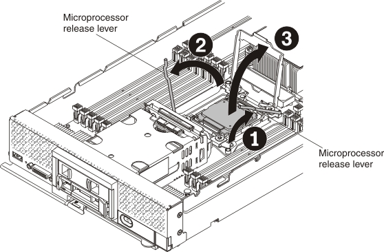
- Identify which release lever is labeled as the first release lever to open (labeled on the microprocessor-retention assembly) and open it.
- Open the second release lever on the microprocessor socket.
- Open the microprocessor retainer.
-
Open the microprocessor socket release levers and retainer
on the replacement system-board assembly.
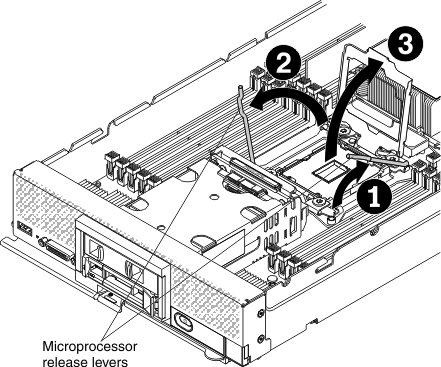
- Identify which release lever is labeled as the first release lever to open (labeled on the microprocessor-retention assembly) and open it.
- Open the second release lever on the microprocessor socket.
- Open the microprocessor retainer.
-
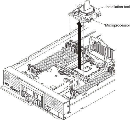
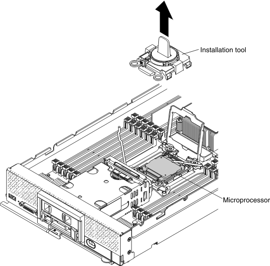
Using the microprocessor installation tool,
remove the microprocessor from the socket on the defective system-board
assembly.
Attention:
- Dropping the microprocessor during installation or removal can damage the contacts.
- Do not touch the connectors on the microprocessor and the microprocessor socket; handle the microprocessor by the edges only. Contaminants on the microprocessor contacts, such as oil from your skin, can cause connection failures between the contacts and the socket.
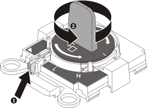
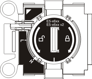
- Select the empty installation tool and make sure that the handle
is in the open position.
If the installation tool handle is not in the open position: 1) lift the interlock latch and hold it up while you 2) twist the microprocessor installation tool handle counterclockwise to the open position, and then release the interlock latch. The following illustration of the installation tool shows the location of the interlock latch and counterclockwise rotation of the handle before loading the microprocessor.
- Align the installation tool with the screws, as shown in the following
graphic, and lower the installation tool on the microprocessor. The
installation tool rests flush on the socket only when it is aligned
correctly.
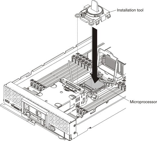
- Gently twist the handle of the installation tool clockwise until
it locks in the
H
orL
position, depending on the size of microprocessor; then, lift the microprocessor out of the socket.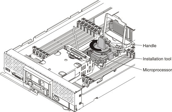
-
Install the microprocessor in the microprocessor socket
on the replacement system-board assembly.
Attention: Do not press the microprocessor into the socket.
- Align the installation tool with the microprocessor socket on
the replacement system-board assembly. The installation tool rests
flush on the socket only if it is properly aligned.
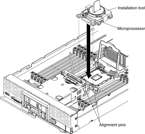
- Twist the handle of the installation tool assembly counterclockwise
until the microprocessor is inserted into the socket, and lift the
installation tool out of the socket.
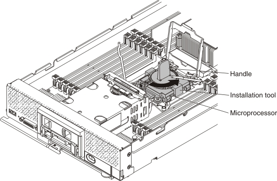
The following illustration shows the installation tool handle in the open position, ready for tool removal.
The following illustration shows removing the installation tool handle.
- Align the installation tool with the microprocessor socket on
the replacement system-board assembly. The installation tool rests
flush on the socket only if it is properly aligned.
-
Close the microprocessor socket release retainer
and levers on the replacement system-board assembly.
Attention: Make sure that the microprocessor is aligned correctly in the socket before you try to close the microprocessor retainer.
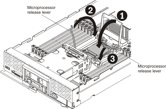
- Close the microprocessor retainer on the microprocessor socket.
- Identify which release lever is labeled as the first release lever to close (labeled on the microprocessor-retention assembly) and close it.
- Close the second release lever on the microprocessor socket.
-
Close the microprocessor socket release retainer and
levers on the defective system-board assembly.
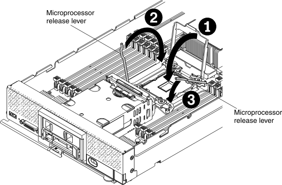
- Close the microprocessor retainer on the microprocessor socket.
- Identify which release lever is labeled as the first release lever to close (labeled on the microprocessor-retention assembly) and close it.
- Close the second release lever on the microprocessor socket.
-
Open the microprocessor socket release levers and retainer
on the defective system-board assembly.
-
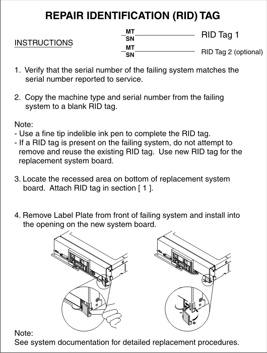
The replacement system-board assembly comes with a Repair
Identification (RID) tag. Using a fine tip indelible ink pen, transfer
the machine type and serial number from the defective system-board
assembly to the label on the Repair Identification tag; then, place
the tag in the recessed area 1 on the bottom of replacement system-board
assembly.
After you transfer components to the replacement system-board assembly, complete the following steps:
- Install the compute node in the chassis (see Installing a compute node in a chassis for instructions).
- Use the CMM Web Interface to restore the IP address of the compute
node IMM. See Starting web interface for
more information. Note: If you configured static IP addresses, you will not be able to access the node remotely or from a management device until the IP address of the IMM is restored.
- Reactivate any Features on Demand features. Instructions for automating the activation of features and installing activation keys is in the Lenovo Features on Demand Users Guide. To download the document, go to the Lenovo Features on Demand website, log in, and click Help.
- Update the Universally Unique Identifier (UUID) and DMI/SMBIOS data with new vital product data (VPD). Use the Advanced Settings Utility to update the UUID and DMI/SMBIOS data (see Updating the Universally Unique Identifier (UUID) and DMI/SMBIOS data with vital product data).
- Update the compute node with the latest firmware or restore the preexisting firmware (see Updating firmware and device drivers for more information).
If you are instructed to return the defective system-board assembly, follow all packaging instructions, and use any packaging materials for shipping that are supplied to you.