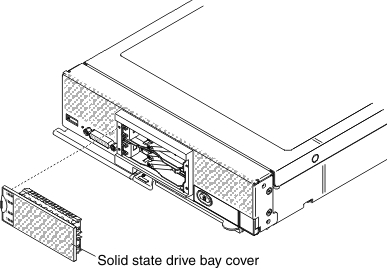
Use this information to install a 1.8-inch hot-swap solid state drive (SSD). Solid state drives can be installed in both the upper and lower compute nodes, if an SSD mounting sleeve is installed.
You can install up to four 1.8-inch solid state drives (SSDs) in a compute node if an optional SSD mounting sleeve is installed in the compute node. At least one 1.8-inch solid state drive must be installed in the SSD mounting sleeve. The 1.8-inch solid-state drives used in the Lenovo Flex System x240 M5 compute node are hot-swap drives.
RAID level-0 (striping) can be configured on a compute node with a single hard disk drive installed. A minimum of two disk drives of the same interface type must be installed to implement and manage RAID level-1 (mirroring) arrays. See Configuring a RAID array for information about RAID configuration. Additional RAID levels are supported if an optional RAID controller is installed in the compute node.
Before you install a 1.8-inch hot-swap solid state drive, read Safety and Installation guidelines.
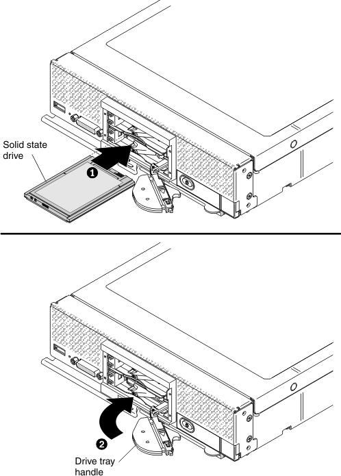
To install a 1.8-inch hot-swap solid state drive, complete the following steps:
-
For the solid state drive that you want to install, slide
the release latch and rotate the loose end of the drive tray handle
away from the compute node. Hook the recess on the drive tray handle
on the tab on the right side of the solid state drive mounting sleeve
to hold the drive tray handle in the open position.
-
Repeat step 3 to step 6 for each solid state drive
being installed.