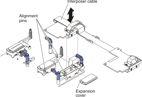
Use this information to remove an interposer cable.
Before you remove the interposer cable,
complete the following steps:
- Read Safety and Installation guidelines.
- If the compute node is installed in a chassis, remove it (see Removing a compute node from a chassis for instructions).
- Carefully lay the compute node on a flat, static-protective surface, orienting the compute node with the bezel pointing toward you.
To remove an interposer cable, complete the following steps.
Note: Some expansion nodes
require an interposer cable that might be part of the expansion node.
See the documentation that comes with your expansion node for additional
information and instructions for removing this type of interposer
cable (see Flex System expansion node).
If you are instructed to return the interposer cable,
follow all packaging instructions, and use any packaging materials
for shipping that are supplied to you.