Use this information to install a microprocessor and heat sink.
Before you begin
Note: This procedure
should be performed only by trained
service technicians.
Before you install a microprocessor
and heat sink, complete the following steps:
- Read Safety and Installation guidelines.
- If the compute node is installed in an Flex System chassis, remove it (see Removing a compute node from a chassis for instructions).
- Carefully lay the compute node on a flat, static-protective surface, orienting the compute node with the bezel pointing toward you.
About this task
The following notes describe the type of microprocessor
that the compute node supports and other information that you must
consider when you install a microprocessor:
- Each microprocessor socket must always contain a microprocessor and heat sink.
- If you are replacing a defective microprocessor, make sure that the microprocessors are identical.
- Before you replace microprocessor, download and install the most current level of UEFI code (see Updating firmware and device drivers).
- The microprocessor installation tool might become worn after several uses. Make sure that the tool can hold the microprocessor securely if you are reusing an existing microprocessor installation tool. Do not return the tool with other parts that you are returning.
- If
you are replacing a defective microprocessor, you must obtain
the following items for use during the replacement procedure (see Parts listing, Types 7903 and 4259):
- Alcohol wipes
- Thermal grease
- If you are replacing a defective microprocessor, the CRU kit comes with one installation tool with the replacement microprocessor installed on it and a cover over the microprocessor, and one empty installation tool without a cover.
- The
microprocessor installation tool has the microprocessor
installed on the tool, and may have a protective cover over the microprocessor.
Do not use the tool, or remove the cover until you are instructed
to do so.Note: Be sure to use the installation tool that comes with your microprocessor installation tool assembly.
Attention:
- Do not use any tools or sharp objects to lift the locking levers on the microprocessor socket. Doing so might result in permanent damage to the system board.
- Do not touch the contacts in the microprocessor socket. Touching these contacts might result in permanent damage to the system board.
Procedure
To install a microprocessor and heat sink, complete the following steps:
-
Open the microprocessor socket release levers and retainer.
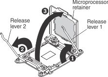
- Identify which release lever is labeled as the first release lever to open and open it.
- Open the second release lever on the microprocessor socket.
- Open the microprocessor retainer.
-
Install the microprocessor in the microprocessor
socket.
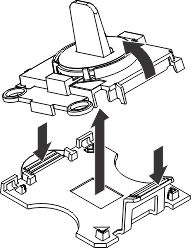
-
Open the packaging that contains the new microprocessor
installation tool assembly and carefully remove the installation tool
assembly from the package.
 Note: Do not touch the microprocessor contacts. Contaminants on the microprocessor contacts, such as oil from your skin, can cause connection failures between the contacts and the socket.
 -
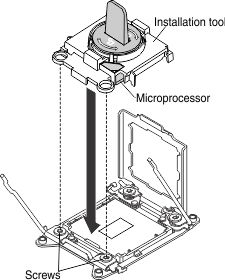
Align the installation tool with the microprocessor
socket. The installation tool rests flush on the socket only if it
is properly aligned.
-
Open the packaging that contains the new microprocessor
installation tool assembly and carefully remove the installation tool
assembly from the package.
-
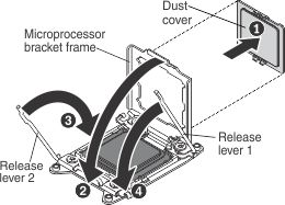
Close the microprocessor retainer and release
levers in the order that is shown.
-
If you are installing a new heat sink,
remove the plastic protective cover from the bottom of the heat sink.
If you are reinstalling a heat sink that you previously removed from
the compute node, make sure that the thermal grease is still on the
bottom of the heat sink and on the top of the microprocessor.
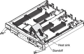
- Position the notched side of the heat sink in the standoff and align the heat sink over the microprocessor. The heat sink is keyed to assist with proper alignment.
- Align and place the heat sink on top of the microprocessor in the retention bracket, thermal grease side down.
- Align the screws on the heat sink with the holes on the heat-sink retention module.
- Press firmly on the heat sink.
- Press firmly on the captive screws and tighten them with a screwdriver, alternating between the screws in a figure-8 pattern, turn each screw one full rotation. You can cause damage to the microprocessor if you tighten the screws on one side first, rather than alternating sides. Each screw should then be tightened two more full rotations. Do not overtighten the screws with excessive force.
What to do next
After you install a microprocessor
and heat sink, complete
the following steps:
- Install the cover (see Installing the compute node cover).
- Install the compute node in a Flex System chassis (see Installing a compute node in a chassis for instructions).