Use this information to install a compute node in a Flex System chassis.
Before you begin
Before you install the compute node in a chassis, read Safety and Installation guidelines.
Statement 21
CAUTION:
Hazardous energy is present when the compute node is
connected to the power source. Always replace the compute node cover
before installing the compute node.
If you are installing
a compute node model that does not have an integrated Ethernet controller,
you must install a network interface adapter before you install the
compute node in the chassis for management network communication.
For a list of supported optional devices for the compute node, see the ServerProven website.
Procedure
To install the compute node in a chassis, complete the
following steps.
-
Select the node bay.
Notes:
- If you are reinstalling a compute node that you removed, you must
install it in the same node bay from which you removed it. Some compute
node configuration information and update options are established
according to node bay number. Reinstalling a compute node into a different
node bay can have unintended consequences. If you reinstall the compute
node into a different node bay, you might have to reconfigure the
compute node.
- To maintain proper system cooling, do not operate the Flex System chassis
without a compute node or node bay filler in each node bay.
- If you plan to configure nodes to form a multi-node
complex, the lowest node bay ID is the primary node in the scalable
partition. The other nodes are the secondary nodes.
- If you purchased a multi-node complex and you received each compute
node packaged individually, each compute node has a label on the top
of the bezel identifying the primary node and the secondary nodes
as defined at the factory during testing. Install the nodes in the
chassis in the order indicated on the label.
- If you plan to configure a scalable partition,
you must install and configure compute nodes in the configuration
at the same time.
-
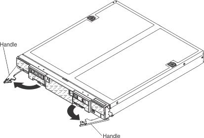
Make sure that the front handles on the compute node are
in the open position.
-
Slide the compute node into the node bay until it stops.
-
Push the front handles on the front of the compute node
to the closed position.
Note: After the compute node is
installed, the IMM2 in the compute node initializes and synchronizes
with the Chassis Management Module. This process takes approximately
90 seconds to complete. The power LED flashes rapidly, and the power
button on the compute node does not respond until this process is
complete.
-
Optionally, install the SMP expansion connector
(see Installing an SMP expansion connector).
-
Turn on the compute node (see Turning on the compute node for instructions).
-
Make sure that the power LED on the compute node control
panel is lit continuously, indicating that the compute node is receiving
power and is turned on.
-
If you have other compute nodes to install, do so now.
-
You can place identifying information on the label tabs
that are accessible from the front of the compute node.
What to do next
If this is the initial installation of the compute node
in the chassis, you must configure the compute node through the Setup
utility and install the compute node operating system. See
Updating the compute node configuration and Installing the operating system
for details.
If
you have changed the configuration of the compute node or if you are
installing a different compute node from the one that you removed,
you must configure the compute node through the Setup utility, and
you might have to install the compute node operating system (see Using the Setup utility).