Use this information to install a flash DIMM.
Before you begin
- Read Safety and Installation guidelines.
- Read the documentation that comes with the flash DIMMs.
- If the compute node is installed in an Flex System chassis, remove it (see Removing a compute node from a chassis for instructions).
- Carefully lay the compute node on a flat, static-protective surface, orienting the compute node with the bezel pointing toward you.
About this task
This component can be installed as an optional device or as a CRU. The installation procedure is the same for the optional device and the CRU.
The following illustration shows the system-board components, including the DIMM connectors.
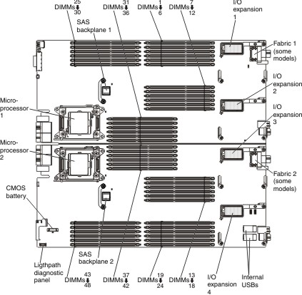
The following notes describe information that you must
consider when you install flash DIMMs:
- Install only 200 GB flash DIMMs or only 400 GB flash DIMMs, mixing of capacities is not supported.
- Install only one flash DIMM per channel with one or two RDIMMs on the same channel.
- You can install 1, 2, 4, 8, 12, or 16 flash DIMMs.
- In two-node and four-node complexes, you can install 1, 2, 4, 8, 12, 16, or 32 flash DIMMs.
- You can install flash DIMMs in only the two nodes in the lowest bay IDs in a four-node complex.
- Flash DIMMs are not supported if lockstep mode, mirrored-channel mode, or rank sparing is enabled.
- Flash DIMMs operate at the same DIMM frequency as the speed of the RDIMMs installed in the compute node.
If RDIMMs are installed, see Table 1 for one-node configurations or Table 2 for multi-node configurations.
| DIMM order | DIMM connector | DIMM type |
|---|---|---|
| 1 | DIMM 28 | RDIMM |
| 2 | DIMM 45 | RDIMM |
| 3 | DIMM 10 | RDIMM |
| 4 | DIMM 15 | RDIMM |
| 5 | DIMM 4 | RDIMM |
| 6 | DIMM 21 | RDIMM |
| 7 | DIMM 33 | RDIMM |
| 8 | DIMM 40 | RDIMM |
| 9 | DIMM 25 | RDIMM |
| 10 | DIMM 48 | RDIMM |
| 11 | DIMM 7 | RDIMM |
| 12 | DIMM 18 | RDIMM |
| 13 | DIMM 1 | RDIMM |
| 14 | DIMM 24 | RDIMM |
| 15 | DIMM 36 | RDIMM |
| 16 | DIMM 37 | RDIMM |
| 17 | DIMM 29 | Flash DIMM |
| 2 | DIMM 44 | Flash DIMM |
| 3 | DIMM 11 | Flash DIMM |
| 4 | DIMM 14 | Flash DIMM |
| 5 | DIMM 5 | Flash DIMM |
| 6 | DIMM 20 | Flash DIMM |
| 7 | DIMM 26 | Flash DIMM |
| 8 | DIMM 47 | Flash DIMM |
| 9 | DIMM 8 | Flash DIMM |
| 10 | DIMM 17 | Flash DIMM |
| 11 | DIMM 2 | Flash DIMM |
| 12 | DIMM 23 | Flash DIMM |
| 13 | DIMM 30 | Flash DIMM |
| 14 | DIMM 43 | Flash DIMM |
| 15 | DIMM 27 | Flash DIMM |
| 16 | DIMM 46 | Flash DIMM |
| DIMM order | DIMM connector | DIMM type |
|---|---|---|
| 1 | DIMM 28 | RDIMM |
| 2 | DIMM 45 | RDIMM |
| 3 | DIMM 10 | RDIMM |
| 4 | DIMM 15 | RDIMM |
| 5 | DIMM 4 | RDIMM |
| 6 | DIMM 21 | RDIMM |
| 7 | DIMM 33 | RDIMM |
| 8 | DIMM 40 | RDIMM |
| 9 | DIMM 25 | RDIMM |
| 10 | DIMM 48 | RDIMM |
| 11 | DIMM 7 | RDIMM |
| 12 | DIMM 18 | RDIMM |
| 13 | DIMM 1 | RDIMM |
| 14 | DIMM 24 | RDIMM |
| 15 | DIMM 36 | RDIMM |
| 16 | DIMM 37 | RDIMM |
| 17 | DIMM 29 | Flash DIMM |
| 18 | DIMM 44 | Flash DIMM |
| 19 | DIMM 11 | RDIMM |
| 20 | DIMM 14 | RDIMM |
| 21 | DIMM 5 | RDIMM |
| 22 | DIMM 20 | RDIMM |
| 23 | DIMM 32 | RDIMM |
| 24 | DIMM 41 | RDIMM |
| 25 | DIMM 26 | Flash DIMM |
| 26 | DIMM 47 | Flash DIMM |
| 27 | DIMM 8 | RDIMM |
| 28 | DIMM 17 | RDIMM |
| 29 | DIMM 2 | RDIMM |
| 30 | DIMM 23 | RDIMM |
| 31 | DIMM 35 | RDIMM |
| 32 | DIMM 38 | RDIMM |
| 33 | DIMM 30 | Flash DIMM |
| 34 | DIMM 43 | Flash DIMM |
| 35 | DIMM 12 | Flash DIMM |
| 36 | DIMM 13 | Flash DIMM |
| 37 | DIMM 6 | Flash DIMM |
| 38 | DIMM 19 | Flash DIMM |
| 39 | DIMM 31 | RDIMM |
| 40 | DIMM 42 | RDIMM |
| 41 | DIMM 27 | Flash DIMM |
| 42 | DIMM 46 | Flash DIMM |
| 43 | DIMM 9 | Flash DIMM |
| 44 | DIMM 16 | Flash DIMM |
| 45 | DIMM 3 | Flash DIMM |
| 46 | DIMM 22 | Flash DIMM |
| 47 | DIMM 34 | RDIMM |
| 48 | DIMM 39 | RDIMM |
Procedure
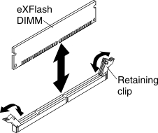
To install a flash DIMM, complete the following steps:
-
Touch the static-protective package that contains the flash
DIMM to any unpainted metal surface on the Flex System chassis
or any unpainted metal surface on any other grounded rack component
in the rack in which you are installing the flash DIMM for at least
2 seconds; then, remove the flash DIMM from the package.
What to do next
After you install the flash DIMM, complete the following
steps:
- Install the cover onto the compute node (see Installing the compute node cover for instructions).
- Install the compute node into the chassis (see Installing a compute node in a chassis for instructions).