Use this information to install a microprocessor and heat
sink.
Note: This procedure should be performed only by trained
service technicians.
Before you install a microprocessor
and heat sink, complete the following steps:
- Read Safety and Installation guidelines.
- If the compute node is installed in a Lenovo Flex System chassis,
remove it (see Removing a compute node from a chassis for instructions).
- Carefully lay the compute node on a flat, static-protective surface,
orienting the compute node with the bezel pointing toward you.
The following notes describe the type of microprocessor
that the compute node supports and other information that you must
consider when you install a microprocessor:
Attention:
- Do not use any tools or sharp objects to lift the locking levers
on the microprocessor socket. Doing so might result in permanent damage
to the system board.
- Do not touch the contacts in the microprocessor socket. Touching
these contacts might result in permanent damage to the system board.
To install a microprocessor and heat sink, complete
the following steps:
- Remove the cover (see Removing the compute node cover).
- Remove the solid
state drives (see Removing a solid state drive).
- Remove the solid
state drive mounting sleeve (see Removing the solid state drive mounting sleeve).
- Remove the solid
state drive cage and backplane (see Removing the solid state drive cage and backplane).
- Remove the hot-swap hard disk drives and
hard disk drive bay fillers (see Removing a hot-swap hard disk drive).
- Remove the hard disk drive cage and backplane
assembly (see Removing the hard disk drive cage and backplane assembly).
- If you are not installing a new microprocessor and a new
heat sink, remove the thermal grease from the heat sink and microprocessor;
then, apply new thermal grease before installation (see Thermal grease).
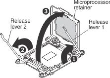
- Open the microprocessor socket release levers and retainer.
- Identify which release lever is labeled as the first
release lever to open and open it.
- Open the second release lever on the microprocessor
socket.
- Open the microprocessor retainer.
- Install the microprocessor in the microprocessor
socket.
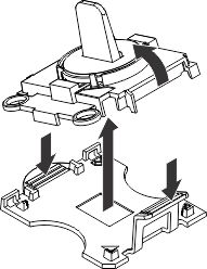
- Open the packaging that contains the new microprocessor
installation tool assembly and carefully remove the installation tool
assembly from the package.
Note: Do
not touch the microprocessor contacts. Contaminants on the microprocessor
contacts, such as oil from your skin, can cause connection failures
between the contacts and the socket.
- Remove the microprocessor protective cover if one is
present.
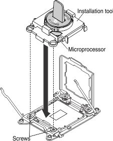
- Align the installation tool with the microprocessor
socket. The installation tool rests flush on the socket only if it
is properly aligned.
- Twist the handle on the microprocessor tool counterclockwise
to insert the microprocessor into the socket. The microprocessor is
keyed to ensure that the microprocessor is installed correctly.
Attention: - Do not press the microprocessor into the socket.
- Make sure that the microprocessor is oriented and aligned correctly
in the socket before you try to close the microprocessor retainer.
- Do not touch the thermal material on the bottom of the heat sink
or on top of the microprocessor. Touching the thermal material will
contaminate it.
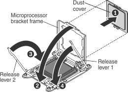
- Close the microprocessor retainer and release
levers in the order that is shown.
- Remove the microprocessor dust cover.
- Close the microprocessor retainer on the microprocessor
socket.
- Identify which release lever is labeled as the first
release lever to close, and close it.
- Close the second release lever on the microprocessor
socket.
Attention: - If you are installing a new heat sink, do not set down the heat
sink after you remove the plastic cover.
- Do not touch the thermal grease on the bottom of the heat sink.
Touching the thermal grease will contaminate it.
- If you are installing a new heat sink,
remove the plastic protective cover from the bottom of the heat sink.
If you are reinstalling a heat sink that you previously removed from
the compute node, make sure that the thermal grease is still on the
bottom of the heat sink and on the top of the microprocessor.
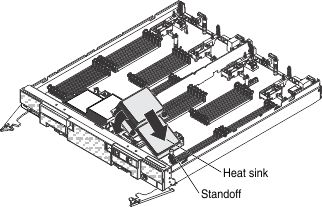
- Position the notched side of the heat
sink in the standoff and align the heat sink over the microprocessor.
The heat sink is keyed to assist with proper alignment.
- Align and place the heat sink on top of the microprocessor
in the retention bracket, thermal grease side down.
- Align the screws on the heat sink with the holes on
the heat-sink retention module.
- Press firmly on the heat sink.
- Press firmly on the captive screws and tighten them
with a screwdriver, alternating between the screws in a figure-eight
pattern, turn each screw one full rotation. You can cause damage to
the microprocessor if you tighten the screws on one side first, rather
than alternating sides. Each screw should then be tightened two more
full rotations. Do not overtighten the screws with excessive force.
- Install the solid
state drive mounting sleeve and solid state drive cage and backplane
(Installing the solid state drive mounting sleeve and Installing the solid state drive cage and backplane).
- Install the solid
state drives (see Installing a solid state drive).
- Install the hard disk drive cage and backplane
assembly (see Installing the hard disk drive cage and backplane assembly)
- Install the hot-swap hard disk drives and
hard disk drive bay fillers (see Installing a hot-swap hard disk drive).