Locate and identify the hardware components, cable part numbers, power distribution unit (PDU) part number, and port-to-port cabling sequence in a dual EN4093R 10 Gb Ethernet scalable switches and in an Storwize V7000 (Lenovo Converged System single-chassis configuration). This configuration is also known as configuration 7V.
The following indexed diagrams help you map a hardware
component to its position on the unit and understand port-to-port
cabling sequence between the components. Use these diagrams with the
tables that follow.
Note: To locate and identify the hardware components,
types of ports, and port numbers in an Lenovo Converged System, see Identifying hardware components in a Lenovo Converged System.
Figure 1. EN4093R 10 GbE scalable switch cabling for Storwize V7000 control
enclosure 1 and 16 Gb SAN Fibre Channel scalable switch
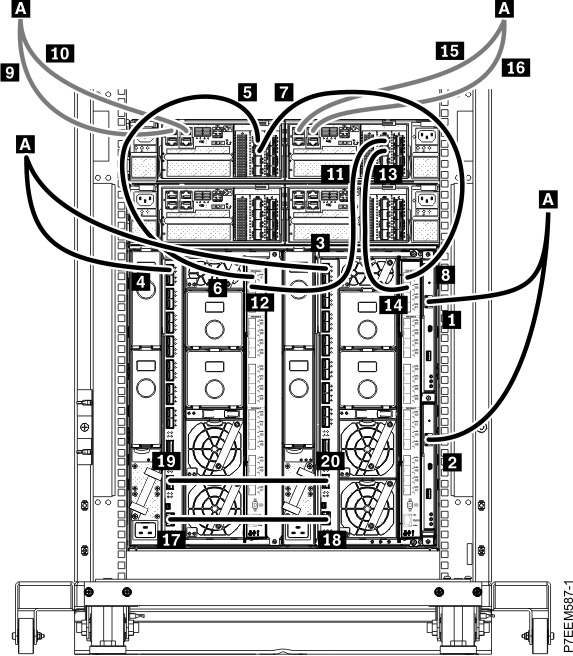
| Index | From: (U-Loc) | Port type (bandwidth) | Cable type | Cable part number | Index | To: (U-Loc) | Port type (bandwidth) |
|---|---|---|---|---|---|---|---|
| 1 | Flex System Chassis Management Module (CMM) 1, chassis 1 (U2) | RJ-45 (1 Gbps) | Cat5e | Use the proper cable | A | To customer network | |
| 2 | CMM 2, chassis 1 (U2) | RJ-45 (1 Gbps) | Cat5e | Use the proper cable | A | To customer network | |
| 3 | Port 1 in 10 GbE scalable switch module, chassis 1, bay 2 (U2) | Small form-factor pluggable (SFP)+ (1 Gbps) | Cat5e | Use the proper cable | A | To customer network | |
| 4 | Port 1 in 10 GbE scalable switch module, chassis 1, bay 1 (U2) | SFP+ (1 Gbps) | Cat5e | Use the proper cable | A | To customer network | |
| Storwize V7000 control enclosure 1 | |||||||
| 5 | Port 1 in canister 1 or controller A in Storwize V7000 control enclosure (U18) | Fibre Channel (8 Gbps) | 1 m (3.2 ft) or 1.5 m (4.9 ft) Fibre Channel cable | Check the cable label to determine the part number. | 6 | Port 0 in Flex System 16 Gb SAN Fibre Channel scalable switch module, chassis 1, bay 3 (U2) | RJ-45 (8 Gbps) |
| 7 | Port 2 in canister 1 or controller A in Storwize V7000 control enclosure (U18) | Fibre Channel (8 Gbps) | 8 | Port 0 in Flex System 16 Gb SAN Fibre Channel scalable switch module, chassis 1, bay 4 (U2) | RJ-45 (8 Gbps) | ||
| 9 | Port 1 in canister 1 or controller A in Storwize V7000 control enclosure (U18) | RJ-45 (1 Gbps) | Cat5e | Use the proper cable | A | To customer network | |
| 10 | Port 2 in canister 1 or controller A in Storwize V7000 control enclosure (U18) | RJ-45 (1 Gbps) | Cat5e | Use the proper cable | A | To customer network | |
| 11 | Port 1 in canister 2 or controller B in Storwize V7000 control enclosure (U18) | Fibre Channel (8 Gbps) | 1 m (3.2 ft) or 1.5 m (4.9 ft) Fibre Channel cable | Check the cable label to determine the part number. | 12 | Port 29 in Flex System 16 Gb SAN Fibre Channel scalable switch module, chassis 1, bay 3 (U2) | RJ-45 (8 Gbps) |
| 13 | Port 2 in canister 2 or controller B in Storwize V7000 control enclosure (U18) | Fibre Channel (8 Gbps) | 14 | Port 29 in Flex System 16 Gb SAN Fibre Channel scalable switch module, chassis 1, bay 4 (U2) | RJ-45 (8 Gbps) | ||
| 15 | Port 1 in canister 2 or controller B in Storwize V7000 control enclosure (U18) | RJ-45 (1 Gbps) | Cat5e | Use the proper cable | A | To customer network | |
| 16 | Port 2 in canister 2 or controller B in Storwize V7000 control enclosure (U18) | RJ-45 (1 Gbps) | Cat5e | Use the proper cable | A | To customer network | |
| EN4093R 10 GbE scalable switch | |||||||
| 17 | Management port in 10 GbE scalable switch module, chassis 1, bay 1 (U2) | RJ-45 (1 Gbps) | 1.5 m (4.9 ft) blue Cat5e | 40K8967 | 18 | Management port in 10 GbE scalable switch module, chassis 1, bay 2 (U2) | RJ-45 (1 Gbps) |
| 19 | Port 19 in 10 GbE scalable switch module, chassis 1, bay 1 (U2) | Quad small form-factor pluggable (QSFP)+ (40 Gbps) | 1 m (3.2 ft) QSFP+ to QSFP+ | 49Y7934 | 20 | Port 19 in 10 GbE scalable switch module, chassis 1, bay 2 (U2) | QSFP+ (40 Gbps) |
Figure 2. EN4093R 10 GbE scalable switch cabling for Storwize V7000 control
enclosure 2 and 16 Gb SAN Fibre Channel scalable switch
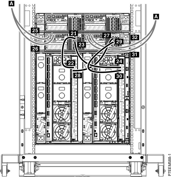
| Index | From: (U-Loc) | Port type (bandwidth) | Cable type | Cable part number | Index | To: (U-Loc) | Port type (bandwidth) |
|---|---|---|---|---|---|---|---|
| Storwize V7000 control enclosure 2 (optional) | |||||||
| 21 | Port 1 in canister 1 or controller A in Storwize V7000 control enclosure (U18) | Fibre Channel (8 Gbps) | 1 m (3.2 ft) or 1.5 m (4.9 ft) Fibre Channel cable | Check the cable label to determine the part number. | 22 | Port 30 in Flex System 16 Gb SAN Fibre Channel scalable switch module, chassis 1, bay 3 (U2) | RJ-45 (8 Gbps) |
| 23 | Port 2 in canister 1 or controller A in Storwize V7000 control enclosure (U18) | Fibre Channel (8 Gbps) | 24 | Port 30 in Flex System 16 Gb SAN Fibre Channel scalable switch module, chassis 1, bay 4 (U2) | RJ-45 (8 Gbps) | ||
| 25 | Port 1 in canister 1 or controller A in Storwize V7000 control enclosure (U18) | RJ-45 (1 Gbps) | Cat5e | Use the proper cable | A | To customer network | |
| 26 | Port 2 in canister 1 or controller A in Storwize V7000 control enclosure (U18) | RJ-45 (1 Gbps) | Cat5e | Use the proper cable | A | To customer network | |
| 27 | Port 1 in canister 2 or controller B in Storwize V7000 control enclosure (U18) | Fibre Channel (8 Gbps) | 1 m (3.2 ft) or 1.5 m (4.9 ft) Fibre Channel cable | Check the cable label to determine the part number. | 28 | Port 31 in Flex System 16 Gb SAN Fibre Channel scalable switch module, chassis 1, bay 3 (U2) | RJ-45 (8 Gbps) |
| 29 | Port 2 in canister 2 or controller B in Storwize V7000 control enclosure (U18) | Fibre Channel (8 Gbps) | 30 | Port 31 in Flex System 16 Gb SAN Fibre Channel scalable switch module, chassis 1, bay 4 (U2) | RJ-45 (8 Gbps) | ||
| 31 | Port 1 in canister 2 or controller B in Storwize V7000 control enclosure (U18) | RJ-45 (1 Gbps) | Cat5e | Use the proper cable | A | To customer network | |
| 32 | Port 2 in canister 2 or controller B in Storwize V7000 control enclosure (U18) | RJ-45 (1 Gbps) | Cat5e | Use the proper cable | A | To customer network | |
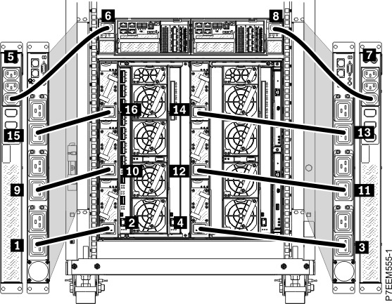
Figure 3. 32 A single-phase power distribution unit (PDU) cabling
| Index | From | Connector type | Cable type | Cable part number | Index | To | Connector type |
|---|---|---|---|---|---|---|---|
| PDU part number: 42R8744 (North America only), 42R8743 (worldwide) | |||||||
| 1 | Outlet 6 in PDU 1 (front) | C19 | 16 A, 100-240 V power cord | Check the power cord label to determine the part number. | 2 | Power supply module, bay 4 | C20 |
| 3 | Outlet 6 in PDU 2 (front) | C19 | 16 A, 100-240 V power cord | 4 | Power supply module, bay 1 | C20 | |
| 5 | Outlet 1A in PDU 1 (rear) | C13 | 10 A, 200-240 V power cord | 6 | Canister 1 in Storwize V7000 controller (rear) | C14 | |
| 7 | Outlet 1A in PDU 2 (rear) | C13 | 10 A, 200-240 V power cord | 8 | Canister 2 in Storwize V7000 controller (rear) | C14 | |
| 9 | Outlet 4 in PDU 1 (front) | C19 | 16 A, 100-240 V power cord | 10 | Power supply module, bay 5 | C20 | |
| 11 | Outlet 4 in PDU 2 (front) | C19 | 16 A, 100-240 V power cord | 12 | Power supply module, bay 2 | C20 | |
| 13 | Outlet 6 in PDU 3 (front) | C19 | 16 A, 100-240 V power cord | 14 | Power supply module, bay 3 | C20 | |
| 15 | Outlet 6 in PDU 4 (front) | C19 | 16 A, 100-240 V power cord | 16 | Power supply module, bay 6 | C20 | |
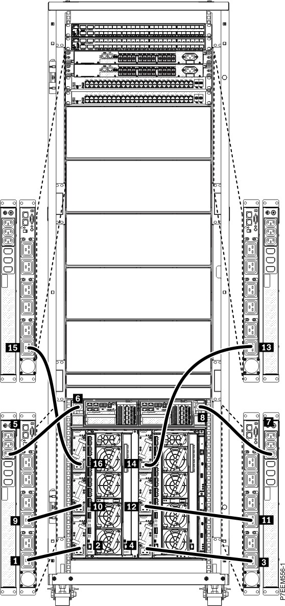
Figure 4. 32 A three-phase PDU cabling
| Index | From | Connector type | Cable type | Cable part number | Index | To | Connector type |
|---|---|---|---|---|---|---|---|
| PDU part number: 42R8744 (North America only), 42R8743 (worldwide) | |||||||
| 1 | Outlet 6 in PDU 1 (front) | C19 | 16 A, 100-240 V power cord | Check the power cord label to determine the part number. | 2 | Power supply module, bay 4 | C20 |
| 3 | Outlet 6 in PDU 2 (front) | C19 | 16 A, 100-240 V power cord | 4 | Power supply module, bay 1 | C20 | |
| 5 | Outlet 1A in PDU 1 (rear) | C13 | 10 A, 200-240 V power cord | 6 | Canister 1 in Storwize V7000 controller (rear) | C14 | |
| 7 | Outlet 1A in PDU 2 (rear) | C13 | 10 A, 200-240 V power cord | 8 | Canister 2 in Storwize V7000 controller (rear) | C14 | |
| 9 | Outlet 4 in PDU 1 (front) | C19 | 16 A, 100-240 V power cord | 10 | Power supply module, bay 5 | C20 | |
| 11 | Outlet 4 in PDU 2 (front) | C19 | 16 A, 100-240 V power cord | 12 | Power supply module, bay 2 | C20 | |
| 13 | Outlet 2 in PDU 2 (front) | C19 | 16 A, 100-240 V power cord | 14 | Power supply module, bay 3 | C20 | |
| 15 | Outlet 2 in PDU 1 (front) | C19 | 16 A, 100-240 V power cord | 16 | Power supply module, bay 6 | C20 | |