Locate and identify the hardware components in an Lenovo Converged System.
The following indexed diagrams help you map a hardware component to its position on the unit in a Lenovo Converged System. Use these diagrams with the following tables.
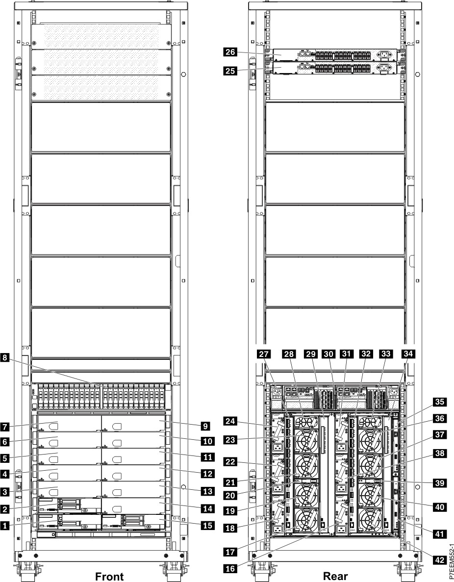
Lenovo Converged System assembly
Figure 1. Lenovo Converged System assembly details
| Index number | Description |
|---|---|
| 1 | Flex System Manager |
| 2 | Compute node |
| 3 - 7 | Bays 3 - 7 (front) |
| 8 | Storwize V7000 control enclosure (front) |
| 9 - 14 | Bay 9 - 14 (front) |
| 15 | Compute node |
| 16 | Power supply module, bay 1 |
| 17 | Fan, bay 6 |
| 18 | Power supply module, bay 4 |
| 19 | Fan, bay 7 |
| 20 | Fan logic, bay 2 |
| 21 | Fan, bay 8 |
| 22 | Power supply module, bay 5 |
| 23 | Fan, bay 9 |
| 24 | Power supply module, bay 6 |
| 25 | 8 Gb Brocade Fibre Channel switch SAN24B |
| 26 | 8 Gb Brocade Fibre Channel switch SAN24B |
| 27 | I/O module, bay 1 |
| 28 | Fan, bay 10 |
| 29 | I/O module, bay 3 |
| 30 | Storwize V7000 control enclosure (rear) |
| 31 | Power supply module, bay 3 |
| 32 | I/O module, bay 2 |
| 33 | Fan, bay 5 |
| 34 | I/O module, bay 4 |
| 35 | Flex System Chassis Management Module (CMM), bay 2 |
| 36 | Fan, bay 4 |
| 37 | Fan, bay 3 |
| 38 | Power supply module, bay 2 |
| 39 | Fan logic, bay 1 |
| 40 | Fan, bay 2 |
| 41 | CMM, bay 1 |
| 42 | Fan, bay 1 |
Storage
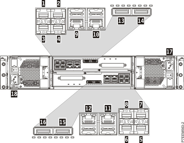
Figure 2. Storwize V7000 control enclosure
| Index number | Description |
|---|---|
| 1 | Small form-factor pluggable (SFP)+ port 1 (canister 1 or controller A) |
| 2 | SFP+ port 2 (canister 1 or controller A) |
| 3 | SFP+ port 3 (canister 1 or controller A) |
| 4 | SFP+ port 4 (canister 1 or controller A) |
| 5 | SFP+ port 1 (canister 2 or controller B) |
| 6 | SFP+ port 2 (canister 2 or controller B) |
| 7 | SFP+ port 3 (canister 2 or controller B) |
| 8 | SFP+ port 4 (canister 2 or controller B) |
| 9 | 1 GbE RJ-45 port 1 (canister 1 or controller A) |
| 10 | 1 GbE RJ-45 port 2 (canister 1 or controller A) |
| 11 | 1 GbE RJ-45 port 1 (canister 2 or controller B) |
| 12 | 1 GbE RJ-45 port 2 (canister 2 or controller B) |
| 13 | SAS port 1 (canister 1 or controller A) |
| 14 | SAS port 2 (canister 1 or controller A) |
| 15 | SAS port 1 (canister 2 or controller B) |
| 16 | SAS port 2 (canister 2 or controller B) |
| 17 | C14 connector (canister 1 or controller A) |
| 18 | C14 connector (canister 2 or controller B) |
Network devices
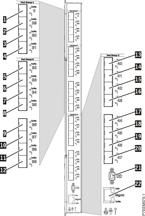
Figure 3. Flex System 16 Gb SAN Fibre Channel scalable switch
| Index number | Description |
|---|---|
| 1 | External Fibre Channel port 0 |
| 2 - 4 | External Fibre Channel ports 29 - 31 |
| 5 - 8 | External Fibre Channel ports 32 - 35 |
| 9 - 12 | External Fibre Channel ports 36 - 39 |
| 13 - 16 | External Fibre Channel ports 40 - 43 |
| 17 -20 | External Fibre Channel ports 44 - 47 |
| 21 | Mini Universal Serial Bus (USB) console port |
| 22 | Ethernet port |
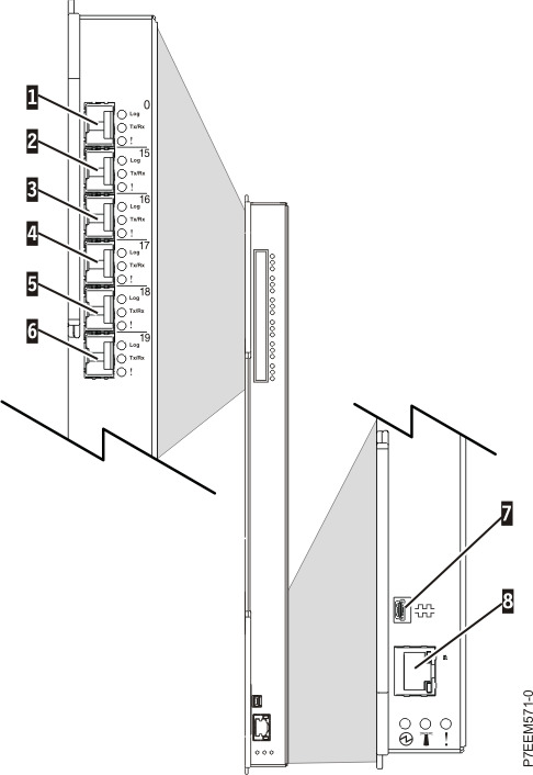
Figure 4. QLogic 8 Gb Fibre Channel scalable switch
| Index number | Description |
|---|---|
| 1 | External Fibre Channel port 0 |
| 2 | External Fibre Channel port 15 |
| 3 | External Fibre Channel port 16 |
| 4 | External Fibre Channel port 17 |
| 5 | External Fibre Channel port 18 |
| 6 | External Fibre Channel port 19 |
| 7 | Serial port |
| 8 | Ethernet port |
Figure 5. CN4093 10 Gb converged scalable switch
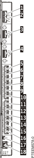
| Index number | Description |
|---|---|
| 1 | 10 GbE SFP+ port 1 |
| 2 | 10 GbE SFP+ port 2 |
| 3 | 10 Gb quad small form-factor pluggable (QSFP)+ ports 3 - 6 |
| 4 | 10 Gb QSFP+ ports 7 - 10 |
| 5 | 10 GbE Omni port 11 |
| 6 | 10 GbE Omni port 12 |
| 7 | 10 GbE Omni port 13 |
| 8 | 10 GbE Omni port 14 |
| 9 | 10 GbE Omni port 15 |
| 10 | 10 GbE Omni port 16 |
| 11 | 10 GbE Omni port 17 |
| 12 | 10 GbE Omni port 18 |
| 13 | 10 GbE Omni port 19 |
| 14 | 10 GbE Omni port 20 |
| 15 | 10 GbE Omni port 21 |
| 16 | 10 GbE Omni port 22 |
| 17 | RS-232 serial management port |
| 18 | 1 GbE RJ-45 port |
Figure 6. EN4093R 10 GbE scalable switch
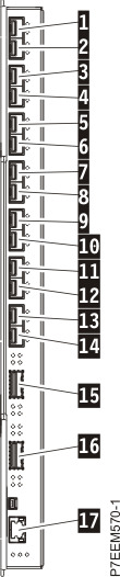
| Index number | Description |
|---|---|
| 1 | 10 GbE SFP+ port 1 |
| 2 | 10 GbE SFP+ port 2 |
| 3 | 10 GbE SFP+ port 3 |
| 4 | 10 GbE SFP+ port 4 |
| 5 | 10 GbE SFP+ port 5 |
| 6 | 10 GbE SFP+ port 6 |
| 7 | 10 GbE SFP+ port 7 |
| 8 | 10 GbE SFP+ port 8 |
| 9 | 10 GbE SFP+ port 9 |
| 10 | 10 GbE SFP+ port 10 |
| 11 | 10 GbE SFP+ port 11 |
| 12 | 10 GbE SFP+ port 12 |
| 13 | 10 GbE SFP+ port 13 |
| 14 | 10 GbE SFP+ port 14 |
| 15 | 40 GbE QSFP ports 15 - 18 |
| 16 | 40 GbE QSFP ports 19 - 22 |
| 17 | 1 GbE RJ-45 port |
Figure 7. 8 Gb Brocade Fibre Channel switch SAN24B scalable switch details
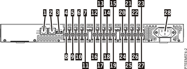
| Index number | Description |
|---|---|
| 1 | 1 GbE RJ-45 port |
| 2 | 1 GbE RJ-45 port |
| 3 | Universal Serial Bus (USB) port |
| 4 - 11 | 8 GbE SFP+ ports 0 - 7 |
| 12 - 19 | 8 GbE SFP+ ports 8 - 15 |
| 20 - 27 | 8 GbE SFP+ ports 16 - 23 |
| 28 | Power receptacle |