Use this information to remove a microprocessor-retention
assembly.
Before you begin
Note: This procedure should be performed only by trained service
technicians.
Before you remove the microprocessor-retention
assembly, complete the following steps:
- Read Safety and Installation guidelines.
- If the compute node is installed in an Flex System chassis,
remove it (see Removing a compute node from a chassis for
instructions).
- Carefully lay the compute node on a flat, static-protective surface,
orienting the compute node with the bezel pointing toward you.
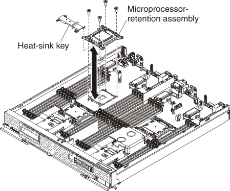
Procedure
To remove a microprocessor-retention assembly, complete
the following steps.
-
Remove the cover (see Removing the compute node cover).
-
Locate the microprocessor socket on the system board.
-
If a microprocessor and heat sink are installed, remove
them (see Removing a microprocessor and heat sink).
-
Remove the heat-sink key from the microprocessor-retention
assemblies and store it in a safe place.
-
Make sure that the microprocessor socket release levers
are in the open position.
-
Using a T20 Torx screwdriver, remove the four screws that
secure the microprocessor-retention assembly.
Attention:
- Do not allow the microprocessor-retention assembly to touch the
microprocessor socket. Doing so might result in permanent damage
to the system board.
- Do not touch the contacts in the microprocessor socket. Touching
these contacts might result in permanent damage to the system board.
-
Lift the microprocessor-retention assembly from the system
board.
What to do next
If you are instructed to return the microprocessor-retention
assembly, follow all packaging instructions, and use any packaging
materials for shipping that are supplied to you.