Use this information to remove a microprocessor and heat sink.
Before you begin
Note: This procedure should be performed only by trained
service technicians.
Before you remove the microprocessor
and heat sink, complete the following steps:
- Read Safety and Installation guidelines.
- If the compute node is installed in an Flex System chassis, remove it (see Removing a compute node from a chassis for instructions).
- Carefully lay the compute node on a flat, static-protective surface, orienting the compute node with the bezel pointing toward you.
About this task
The following notes describe information that you must
consider when you remove a microprocessor:
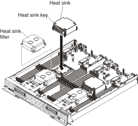
- A socket cover and heat-sink filler or a microprocessor and heat sink must always be installed on microprocessor sockets 1, 3, and 4. Microprocessor socket 2 will only have a socket cover when a microprocessor is not install. If the compute node has only one microprocessor, it must be installed in microprocessor socket 1.
- The microprocessor installation tool might become worn after several uses. Make sure that the tool can hold the microprocessor securely if you are reusing an existing microprocessor installation tool. Do not return the tool with other parts that you are returning.
- If you are installing a second microprocessor, the option kit comes with a microprocessor installation tool that you must use when you install a microprocessor. The microprocessor installation tool comes with the replacement microprocessor installed on it and a cover over the microprocessor.
- If you are replacing a defective microprocessor, the CRU kit comes with one installation tool with the replacement microprocessor installed on it and a cover over the microprocessor, and one empty installation tool without a cover.
- If you are replacing a defective microprocessor, you must obtain
the following items for use during the replacement procedure (see Parts listing, Types 7917, 7167, 2590 and 2584):
- Alcohol wipes
- Thermal grease
Note: Be sure to use
the installation tool that comes with your microprocessor installation
tool assembly. The tools are similar in function and design, however
Tool A has one setting for installing one size of microprocessor,
and supports the following families of microprocessors: E5-26xx, E5-46xx.
Installation Tool B has two settings for installing two different
sizes of microprocessors. The settings that are marked on Tool B are "L" for
smaller low core microprocessors, and "H" for larger high core
microprocessors. Installation Tool B supports the following families
of microprocessors: E5-26xx, E5-46xx, E5-26xx v2, E5-46xx v2.
Microprocessor
Installation Tools A and B are shown in the following illustration.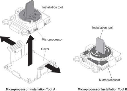
Procedure
To remove a microprocessor and heat sink, complete the following steps.
-
Open the microprocessor socket release levers
and retainer.
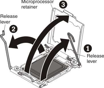
- Identify which release lever is labeled as the first release lever to open, and open it.
- Open the second release lever on the microprocessor socket.
- Open the microprocessor retainer.
Attention: Do not touch the connectors on the microprocessor and the microprocessor socket. -
Remove the microprocessor
from the socket.
-
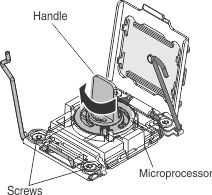
Select the empty installation tool and ensure that the
handle is in the open position. If the installation tool handle is
not in the open position, use the following instructions for your
installation tool:
- If using Installation Tool A, twist the microprocessor installation tool handle counterclockwise to the open position.
- If using Installation Tool B, 1) lift the interlock latch and hold it up while you 2) twist the microprocessor installation tool handle counterclockwise to the open position, and then release the interlock latch. The following illustration of the installation tool shows the location of the interlock latch and counterclockwise rotation of the handle before loading the microprocessor.
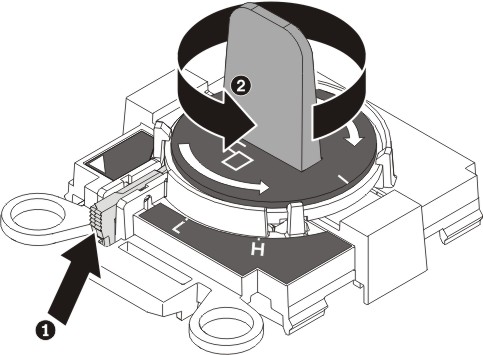
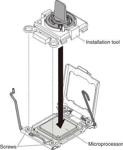
-
Align the installation tool with the screws, as shown
in the following graphic, and lower the installation tool on the microprocessor.
The installation tool rests flush on the socket only when it is aligned
correctly.
-
Using the following instructions for your installation
tool, remove the microprocessor.
- If using Installation Tool A, gently twist the handle clockwise to the closed position and lift the microprocessor out of the socket.
- If using Installation Tool B, gently twist the handle of the installation tool clockwise until it locks in the "H" or "L" position, depending on the size of microprocessor, and then lift the microprocessor out of the socket.
-
Select the empty installation tool and ensure that the
handle is in the open position. If the installation tool handle is
not in the open position, use the following instructions for your
installation tool: