Installing a microprocessor-retention assembly

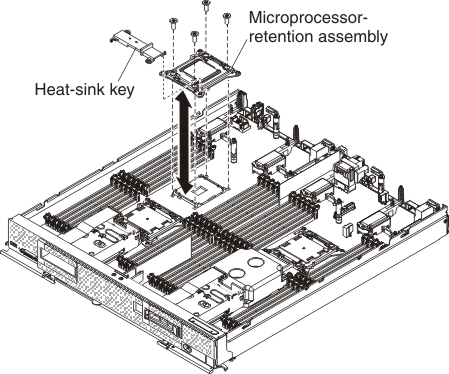
Use this information to install a microprocessor-retention assembly.

Before you begin

Note: This procedure should be performed only by trained service technicians.
Before you install a microprocessor-retention assembly, complete the following steps:
  1. Read Safety and Installation guidelines.
  2. If the compute node is installed in an Flex System chassis, remove it (see Removing a compute node from a chassis for instructions).
  3. Carefully lay the compute node on a flat, static-protective surface, orienting the compute node with the bezel pointing toward you.

Procedure

To install a microprocessor-retention assembly, complete the following steps.

Graphic illustrating installing the microprocessor-retention assembly

  1. Remove the cover (see Removing the compute node cover).
  2. Make sure that the microprocessor socket release levers are in the open position.
  3. Align the microprocessor-retention assembly on the system board.
    Attention:
    1. Do not allow the microprocessor-retention assembly to touch the microprocessor socket. Doing so might result in permanent damage to the system board.
    2. Do not touch the contacts in the microprocessor socket. Touching these contacts might result in permanent damage to the system board.
  4. Using a T20 Torx screwdriver, install the four screws to secure the microprocessor-retention assembly.
  5. Install the heat-sink key on the microprocessor retention assemblies.
  6. If necessary, install the microprocessor and heat sink (see Installing a microprocessor and heat sink).

What to do next

After you install the microprocessor-retention assembly, complete the following steps:
  1. Install the cover onto the compute node (see Installing the compute node cover for instructions).
  2. Install the compute node into the chassis (see Installing a compute node in a chassis for instructions).