Use this information to separate the upper and lower compute nodes of the Flex System x222 Compute Node.
Before you remove the upper compute node, complete the following
steps:
- Read Safety and Installation guidelines.
- If the Flex System x222 Compute Node is installed in a chassis, remove it (see Removing a compute node from a chassis for instructions).
- Carefully lay the compute node on a flat, static-protective surface, orienting the compute node with the bezel pointing toward the left.
- Remove any USB devices or console breakout cables that are connected to the upper or lower compute nodes.
Attention: Make sure that all devices
plugged in to the front of the Flex System x222 Compute Node have
been removed before opening the upper compute node.
Statement 12![]()
CAUTION:
The following label indicates a hot
surface nearby.
![]()
Statement
21![]()
CAUTION:
Hazardous energy is present
when the compute node is connected to the power source. Always replace
the compute node cover before installing the compute node.
Note:
- The upper compute node acts as the cover for the Flex System x222 Compute Node. You can not install the Flex System x222 Compute Node in a chassis unless the upper compute node is installed.
- Although the upper and lower compute nodes are configured and operated independently, they must be installed together as a complete Flex System x222 Compute Node unit.
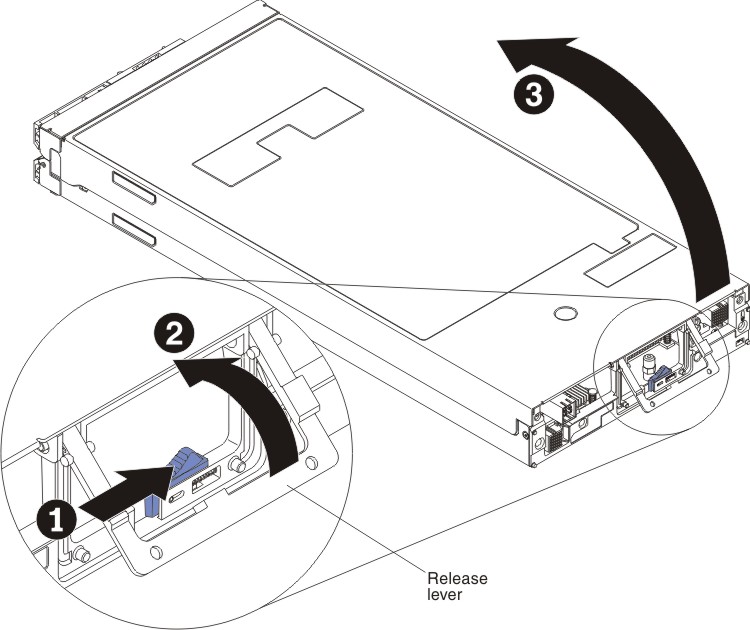
To remove the upper compute node, complete the following steps:
- Lift the upper compute node away from the lower compute
node.