Use this information to install an eXFlash DIMM.
- Read Safety and Installation guidelines.
- Read the documentation that comes with the eXFlash DIMMs.
- If the compute node is installed in a Lenovo Flex System chassis, remove it (see Removing a compute node from a chassis for instructions).
- Carefully lay the compute node on a flat, static-protective surface, orienting the compute node with the bezel pointing toward you.
This component can be installed as an optional device or as a CRU. The installation procedure is the same for the optional device and the CRU.
The following illustration shows
the system-board components, including the DIMM connectors.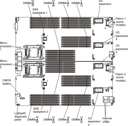
- Install only one eXFlash DIMM per channel with one or two DIMMs
on the same channel.
- The DIMM must always be installed in the terminating DIMM connector of the channel.
- The eXFlash DIMM must be installed in the last channel after all DIMMs are installed. The eXFlash DIMM must be next to the DIMM with no empty DIMM connectors between the DIMM and the eXFlash DIMM.
- The number of DIMMs in a configuration must equal or exceed the number of eXFlash DIMMs.
- Do not install eXFlash DIMMs in DIMM connectors 31 through 42.
- The maximum number of eXFlash DIMMs and DIMMs is 48.
- Install only 200 GB eXFlash DIMMs or only 400 GB eXFlash DIMMs, mixing of capacities is not supported.
- You can install 2, 4, 8, or 12 eXFlash DIMMs in a compute node.
- Lockstep mode, mirrored-channel mode, and rank sparing are not supported when eXFlash DIMMs are installed.
- eXFlash DIMMs operate at the same DIMM frequency as the speed of the DIMMs installed in the compute node.
- In two-node and four-node complexes, you can install a maximum of 24 eXFlash DIMMs.
- You can install eXFlash DIMMs in only the two nodes in the lowest bay IDs in a four-node complex.
- eXFlash DIMMs operate only at 1.5 V.
- For supported operating conditions, see the eXFlash DIMM configuration and support requirements page.
If you plan to install eXFlash DIMMs, install the DIMMs in the Independent mode configuration as described in Table 2.
You install eXFlash DIMMs in groups. The following illustration shows the eXFlash DIMM groups and the DIMM connectors.
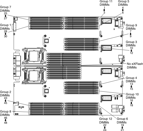
- Install the first eXFlash DIMM in group 1, the next eXFlash DIMM in group 2, and install subsequent eXFlash DIMMs in the next group in sequence.
- For configurations exceeding 32 DIMMs, if all DIMM connectors within a group are populated, install the eXFlash DIMMs starting with the lowest available group number.
- In an unbalanced DIMM configuration (that is, channels populated with unequal numbers of DIMMs), start the installation of the first eXFlash DIMM with the lowest group number containing the smallest number of DIMMs per channel. For example, if group 1 has 2 DIMMs and group 2 has 1 DIMM, start installation of eXFlash DIMMs in group 2. Continue the installation of eXFlash DIMMs in each group in a circular order across the system board.
- Install DIMMs in a balanced configuration (that is, an even number of DIMMs across channels).
- Balance the number of DIMMs and eXFlash DIMMs between microprocessors.
- Install DIMMs in even-numbered quantities.
- For optimal performance, consider the following configurations.
- 8 DIMMs configured with 2 or 4 eXFlash DIMMs
- 16 DIMMs configured with 2, 4, 8, or 12 eXFlash DIMMs
- 32 DIMMs configured with 2, 4, 8, or 12 eXFlash DIMMs
- More than 32 DIMMs might impact memory I/O performance because it creates an unbalanced memory configuration.
The following table shows sample DIMM and eXFlash DIMM configurations.
| Configuration | DIMMs | eXFlash DIMMs |
|---|---|---|
|
DIMM connectors: 28, 25, 10, 15, 4 ,21, 33, 40, 25, 48, 7, 18, 1, 24, 36 ,37 ,29, 44 | eXFlash DIMMs installed in groups: 3, 4 ,5,
6 DIMM connectors: 11, 14, 5, 20 |
|
DIMM connectors: 28, 25, 10, 15, 4, 21, 33, 40 | eXFlash DIMMs installed in groups: 1, 2 DIMM connectors: 29, 44 |
|
DIMM connectors: 28, 25, 10, 15, 4, 21, 33, 40, 25, 48, 7, 18, 1, 24 ,36, 37, 29, 44, 11,14, 5, 20, 32, 41, 26, 47, 8, 17, 2, 23, 35, 38 | eXFlash DIMMs installed in groups: 1, 2, 3,
4, 5, 6, 7, 8, 9, 10, 11, 12 DIMM connectors: 30, 43, 12, 13, 6, 19, 27, 46, 9, 16, 3, 22 |
To install an eXFlash DIMM, complete the following steps:
- Touch the static-protective package that contains the eXFlash
DIMM to any unpainted metal surface on the Lenovo Flex System chassis
or any unpainted metal surface on any other grounded rack component
in the rack in which you are installing the eXFlash DIMM for at least
2 seconds; then, remove the eXFlash DIMM from the package.

- Install the cover onto the compute node (see Installing the compute node cover for instructions).
- Install the compute node into the chassis (see Installing a compute node in a chassis for instructions).