Use this information to install a DIMM.
- Read Safety and Installation guidelines.
- Read the documentation that comes with the DIMMs.
- If the compute node is installed in a Lenovo Flex System chassis, remove it (see Removing a compute node from a chassis for instructions).
- Carefully lay the compute node on a flat, static-protective surface, orienting the compute node with the bezel pointing toward you.
This component can be installed as an optional device or as a CRU. The installation procedure is the same for the optional device and the CRU.
After you install or remove a DIMM, you must change and save the new configuration information by using the Setup utility. When you turn on the compute node, a message indicates that the memory configuration has changed. Start the Setup utility and select Save Settings (see Using the Setup utility for more information) to save changes.
- Verify that the amount of installed memory is the expected amount
of memory through the operating system, by watching the monitor as
the compute node starts, by using the CMM sol command,
or through Flex System Manager management software.
- For more information about the CMM sol command, see the "Flex System Chassis Management Module: Command-Line Interface Reference Guide".
- For more information about Flex System Manager management software, see the "Flex System Manager Software: Installation and Service Guide".
- Run the Setup utility to re-enable the DIMMs (see Using the Setup utility for more information).
The compute node has a total of 48 dual inline memory module (DIMM) connectors. The compute node supports low-profile (LP) DDR3 DIMMs with error-correcting code (ECC) in 8 GB, 16 GB, 32 GB, and 64 GB capacities.
The following illustration shows the system-board components, including the DIMM connectors.
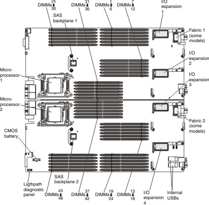
The DDR-3 DIMMs are accessed internally through the integrated memory controllers on the microprocessors. Each microprocessor controls 24 DIMMs. Eight scalable memory buffers provide the interface between the microprocessor memory controller and the DIMMs. The scalable memory controllers interface using one scalable memory interconnect 2 (SMI2) channel. Each SMI2 channel supports two DDR-3 memory buses and each DDR-3 bus connects to up to three DIMMs.
| Microprocessor | SMI2 channel | Scalable memory buffer | DDR channel | DIMM connector |
|---|---|---|---|---|
| Microprocessor 1 | SMI00 | JC00 | DDR0 | 28 |
| 29 | ||||
| 30 | ||||
| DDR1 | 25 | |||
| 26 | ||||
| 27 | ||||
| SMI1 | JC01 | DDR0 | 4 | |
| 5 | ||||
| 6 | ||||
| DDR1 | 1 | |||
| 2 | ||||
| 3 | ||||
| SMI2 | JC02 | DDR0 | 33 | |
| 32 | ||||
| 31 | ||||
| DDR1 | 36 | |||
| 35 | ||||
| 34 | ||||
| SMI3 | JC03 | DDR0 | 10 | |
| 11 | ||||
| 12 | ||||
| DDR1 | 7 | |||
| 8 | ||||
| 9 | ||||
| Microprocessor 2 | SMI0 | JC10 | DDR0 | 15 |
| 14 | ||||
| 13 | ||||
| DDR1 | 18 | |||
| 17 | ||||
| 16 | ||||
| SMI1 | JC11 | DDR0 | 40 | |
| 41 | ||||
| 42 | ||||
| DDR1 | 37 | |||
| 38 | ||||
| 39 | ||||
| SMI2 | JC12 | DDR0 | 21 | |
| 20 | ||||
| 19 | ||||
| DDR1 | 24 | |||
| 23 | ||||
| 22 | ||||
| SMI3 | JC13 | DDR0 | 45 | |
| 44 | ||||
| 43 | ||||
| DDR1 | 48 | |||
| 47 | ||||
| 46 |
- Only 8 GB and 16 GB RDIMMs are supported if you also install eXFlash DIMMs.
- You cannot mix RDIMMs and LRDIMMs in the same compute node.
- You cannot mix RDIMMs and LRDIMMs in a scalable partition within a multi-node complex.
- A total of eight ranks on each channel is supported.
- DIMMs of mixed speed can be installed on different DIMM slots within the same channel, but the DIMMs operate at the speed of the slowest DIMM.
- If you install a quad-rank or octal-rank DIMM, install it in the connector at the end of the memory channel.
- If a channel has one or more quad-rank RDIMMs, only two DIMMs per channel are supported. The quad-rank, eight rank per channel limitation only applies to RDIMMs. You can install three quad-rank LRDIMMs because the microprocessor accesses LRDIMMs as dual-rank DIMMs.
- Independent-channel mode: Independent-channel mode provides high performance memory capability. The memory channels can be populated with DIMMs in any order in independent mode. You can populate all four channels on each microprocessor in any order with no matching requirements. Individual channels can run at different DIMM timings, but all channels must run at the same interface frequency.
- Lockstep mode: Lockstep mode provides extensive memory protection through double device data correction (DDDC). DDDC allows up to two sequential memory DRAM chip failures without affecting overall system performance. The memory controller handles all cache lines across two DDR3 channels controlled by one scalable memory buffer. The SMI2 channel operates at the DDR3 transfer rate.
- Mirrored-channel memory: In mirrored-channel memory, the contents of memory is mirrored between SMI2 channels. As a result, the total available memory is half of the physical memory installed. The maximum effective memory is 1.5 TB (using 64 GB DIMMs). To enable mirrored-channel memory, memory on each SMI2 channel must be populated with DIMMs that have the same feature set (capacity, type, and rank count). The DIMM channels can have memory with different feature sets, but the DIMM slots across each SMI2 channel must be populated with DIMMs that have the same feature set.
- Rank-sparing memory: In rank-sparing memory, one memory
DIMM rank serves as a spare of the other ranks on the same channel.
The spare rank is held in reserve and is not used as active memory.
The spare rank must have identical or larger memory capacity compared
to all the other active DIMM ranks on the same channel. After an error
threshold is surpassed, the contents of that rank are copied to the
spare rank. The failed rank of DIMMs is taken offline, and the spare
rank is put online and used as active memory in place of the failed
rank. The following notes describe additional information that you must consider when you select rank-sparing memory:
- A minimum of two single-rank DIMMs per channel must be populated to use rank-sparing memory.
- You can use rank-sparing memory with single multi-rank DIMMs.
- Rack-sparing memory on one channel is independent of the sparing on all other channels.
- You can use the Setup utility to determine the status of the DIMM ranks.
- If you install LR-DIMMs, more than one rank is held in reserve.
- Rank sparing is not supported when mirroring is enabled.
Install DIMMs in the order that is indicated in the following table for independent-channel mode.
| DIMM order | DIMM connector |
|---|---|
| 1 | DIMM 28 |
| 2 | DIMM 45 |
| 3 | DIMM 10 |
| 4 | DIMM 15 |
| 5 | DIMM 4 |
| 6 | DIMM 21 |
| 7 | DIMM 33 |
| 8 | DIMM 40 |
| 9 | DIMM 25 |
| 10 | DIMM 48 |
| 11 | DIMM 7 |
| 12 | DIMM 18 |
| 13 | DIMM 1 |
| 14 | DIMM 24 |
| 15 | DIMM 36 |
| 16 | DIMM 37 |
| 17 | DIMM 29 |
| 18 | DIMM 44 |
| 19 | DIMM 11 |
| 20 | DIMM 14 |
| 21 | DIMM 5 |
| 22 | DIMM 20 |
| 23 | DIMM 32 |
| 24 | DIMM 41 |
| 25 | DIMM 26 |
| 26 | DIMM 47 |
| 27 | DIMM 8 |
| 28 | DIMM 17 |
| 29 | DIMM 2 |
| 30 | DIMM 23 |
| 31 | DIMM 35 |
| 32 | DIMM 38 |
| 33 | DIMM 30 |
| 34 | DIMM 43 |
| 35 | DIMM 12 |
| 36 | DIMM 13 |
| 37 | DIMM 6 |
| 38 | DIMM 19 |
| 39 | DIMM 31 |
| 40 | DIMM 42 |
| 41 | DIMM 27 |
| 42 | DIMM 46 |
| 43 | DIMM 9 |
| 44 | DIMM 16 |
| 45 | DIMM 3 |
| 46 | DIMM 22 |
| 47 | DIMM 34 |
| 48 | DIMM 39 |
Install DIMMs in the order that is indicated in the following table for lockstep mode.
| Number of DIMM pairs installed | DIMM connectors |
|---|---|
| 1st | DIMMs 25 and 28 |
| 2nd | DIMMs 45 and 48 |
| 3rd | DIMMs 7 and 10 |
| 4th | DIMMs 15 and 18 |
| 5th | DIMMs 1 and 4 |
| 6th | DIMMs 21 and 24 |
| 7th | DIMMs 33 and 36 |
| 8th | DIMMs 37 and 40 |
| 9th | DIMMs 26 and 29 |
| 10th | DIMMs 44 and 47 |
| 11th | DIMMs 8 and 11 |
| 12th | DIMMs 14 and 17 |
| 13th | DIMMs 2 and 5 |
| 14th | DIMMs 20 and 23 |
| 15th | DIMMs 32 and 35 |
| 16th | DIMMs 38 and 41 |
| 17th | DIMMs 27 and 30 |
| 18th | DIMMs 43 and 46 |
| 19th | DIMMs 9 and 12 |
| 20th | DIMMs 13 and 16 |
| 21st | DIMMs 3 and 6 |
| 22nd | DIMMs 19 and 22 |
| 23rd | DIMMs 31 and 34 |
| 24th | DIMMs 39 and 42 |
Install DIMMs in the order that is indicated in the following table for independent-channel mode with mirrored-channel memory.
| Number of DIMM pairs installed | DIMM connectors |
|---|---|
| 1st | DIMMs 4 and 28 |
| 2nd | DIMMs 21 and 45 |
| 3rd | DIMMs 10 and 33 |
| 4th | DIMMs 15 and 40 |
| 5th | DIMMs 1 and 25 |
| 6th | DIMMs 24 and 48 |
| 7th | DIMMs 7 and 36 |
| 8th | DIMMs 18 and 37 |
| 9th | DIMMs 5 and 29 |
| 10th | DIMMs 20 and 40 |
| 11th | DIMMs 11 and 32 |
| 12th | DIMMs 14 and 41 |
| 13th | DIMMs 2 and 26 |
| 14th | DIMMs 23 and 47 |
| 15th | DIMMs 8 and 35 |
| 16th | DIMMs 17 and 38 |
| 17th | DIMMs 6 and 30 |
| 18th | DIMMs 19 and 43 |
| 19th | DIMMs 12 and 31 |
| 20th | DIMMs13 and 42 |
| 21st | DIMMs 3 and 27 |
| 22nd | DIMMs 22 and 46 |
| 23rd | DIMMs 9 and 34 |
| 24th | DIMMs 16 and 39 |
Install DIMMs in the order that is indicated in the following table for lockstep mode with mirrored-channel memory.
| Number of DIMM pairs installed | DIMM connectors |
|---|---|
| 1st | DIMMs 1, 4, 25, and 28 |
| 2nd | DIMMs 21, 24, 45, and 48 |
| 3rd | DIMMs 7, 10, 33, and 36 |
| 4th | DIMMs 15, 18, 37, and 40 |
| 5th | DIMMs 2, 5, 26, and 29 |
| 6th | DIMMs 20, 23, 44, and 47 |
| 7th | DIMMs 8, 11, 32, and 35 |
| 8th | DIMMs 14, 17, 38, and 41 |
| 9th | DIMMs 3, 6, 27, and 30 |
| 10th | DIMMs 19, 22, 43, and 46 |
| 11th | DIMMs 9, 12, 31, and 34 |
| 12th | DIMMs 13, 16, 39, and 42 |
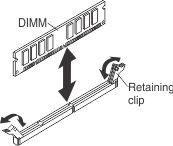
To install a DIMM, complete the following steps:
- Touch the static-protective package that contains the DIMM
to any unpainted metal surface on the Lenovo Flex System chassis
or any unpainted metal surface on any other grounded rack component
in the rack in which you are installing the DIMM for at least 2 seconds;
then, remove the DIMM from the package.
- Install the cover onto the compute node (see Installing the compute node cover for instructions).
- Install the compute node into the chassis (see Installing a compute node in a chassis for instructions).