Use this information for details about the controls, connectors, and LEDs.
The following illustration identifies the buttons, connectors, and LEDs on the control panel.
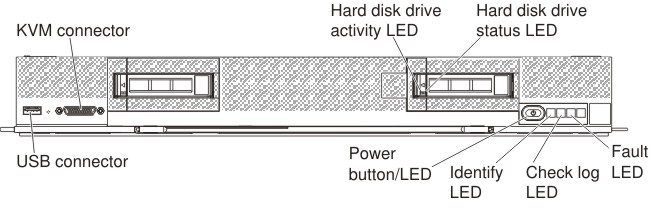
- Fault LED
- When this yellow LED is lit, it indicates
that a system error has occurred in the compute node. In addition,
the fault LED on the chassis system LED panel is lit. You can check
the CMM event log to determine the source of the condition. For more
information, see Viewing event logs without restarting the compute node.
See also Light path diagnostics LEDs for more information about
the LEDs on the compute node.The fault LED turns off only after the error is corrected.Note: When the fault LED turns off, you should also clear the IMM event log. Use the Setup utility to clear the IMM event log.
- Check log LED
When this yellow LED is lit, it indicates that a condition that causes an event to be logged in the event log has occurred. To view the IMM2 event log see IMM event log
The check log LED can be turned off through the CMM led command, the CMM web interface, the Lenovo XClarity Administrator (if available), or the Flex System Manager management software (if available).
- For more information about the CMM led command, see the "Flex System Chassis Management Module: Command-Line Interface Reference Guide".
- From the CMM web interface, select Compute Nodes from the Chassis Management menu. All fields and options are described in the CMM web interface online help. For more information, see the CMM information page.
- For more information about the Lenovo XClarity Administrator, see the Lenovo XClarity Administrator information page.
- For more information about the Flex System Manager management software, see "Flex System Manager Software: Installation and Service Guide".
Note:- Alternatively, you can use the CMM_INDICATES_ITE_ERROR_N command to light the check log LED. See the the Flex System Chassis Management Module: Command-Line Interface Reference Guide for more information.
- You can check the CMM event log to determine the source of the condition. For more information, see Viewing event logs without restarting the compute node.
- Identify LED
- The system administrator can remotely
light this blue LED to aid in visually locating the compute node.
When this LED is lit, the identify LED on the Flex System chassis
is also lit. The identify LED can be lit and turned off through the
CMM led command, the CMM web interface,
the Lenovo XClarity Administrator (if
available), or the Flex System Manager management
software (if
available).
- For more information about the CMM led command, see the "Flex System Chassis Management Module: Command-Line Interface Reference Guide".
- From the CMM web interface, select Compute Nodes from the Chassis Management menu. All fields and options are described in the CMM web interface online help. For more information, see the CMM information page.
- For more information about the Lenovo XClarity Administrator, see the Lenovo XClarity Administrator information page.
- For more information about the Flex System Manager management software, see "Flex System Manager Software: Installation and Service Guide".
- Power button/LED
- When the compute node is connected
to power through the Flex System chassis,
press this button to turn on or turn off the compute node. Note: The power button works only if local power control is enabled for the compute node. Local power control is enabled and disabled through the CMM power command and the CMM web interface.
- For more information about the CMM power command, see the "Flex System Chassis Management Module: Command-Line Interface Reference Guide".
- From the CMM web interface, select Compute Nodes from the Chassis Management menu. For more information, see the "Flex System Chassis Management Module: User's Guide". All fields and options are described in the CMM web interface online help.
After the compute node is removed from the chassis, press and hold this button to activate the system-board LEDs (light path diagnostics). See Compute node controls, connectors, and LEDs for more information.
This button is also the power LED. This green LED indicates the power status of the compute node:- Flashing rapidly: The LED flashes rapidly for one of the
following reasons:
- The compute node has been installed in a chassis. When you install the compute node, the LED flashes rapidly for up to 90 seconds while the integrated management module II (IMM2) in the compute node is initializing and synchronizing with the chassis management module.
- Power permissions have not been assigned to the compute node through the Chassis Management Module.
- The Flex System chassis does not have enough power to turn on the compute node.
- The IMM2 in the compute node is not communicating with the Chassis Management Module.
- Flashing slowly: The compute node is connected to power through the Flex Systemchassis and is ready to be turned on.
- Lit continuously: The compute node is connected to power through the Flex Systemchassis and is turned on.
When the compute node is on, pressing this button causes an orderly shutdown of the compute node so that it can be removed safely from the chassis. This includes shutting down the operating system (if possible) and removing power from the compute node.
If an operating system is running, you might have to press the button for approximately 4 seconds to initiate the shutdown.
Attention: Pressing the button for 4 seconds forces the operating system to shut down immediately. Data loss is possible. - NMI button
- The NMI button is recessed and can be accessed only by using a small pointed device. Pressing this button causes a nonmaskable interrupt for debugging purposes.
- KVM connector
- Connect the console breakout cable to this connector (see Console breakout cable for more information).
- USB connector
- Connect a USB device to this connector.