Removing a PCIe Expansion Node and attached compute node host

Use these instructions to remove a PCIe Expansion Node from a Flex System Enterprise Chassis.

Before you remove a PCIe Expansion Node, complete the following steps:
  1. Read Safety and Installation guidelines.
  2. If the compute node that the PCIe Expansion Node is connected to is operating, shut down the operating system.
  3. Press the power button to turn off the compute node (see the compute node Installation and Service Guide for more information).
Statement 4
Graphic illustrating safety practices when lifting

Graphic illustrating Safety Statement 4

Graphic illustrating Safety Statement 4

Graphic illustrating Safety Statement 4
≥ 18 kg (39.7 lb) ≥ 32 kg (70.5 lb) ≥ 55 kg (121.2 lb)
CAUTION:
Use safe practices when lifting.

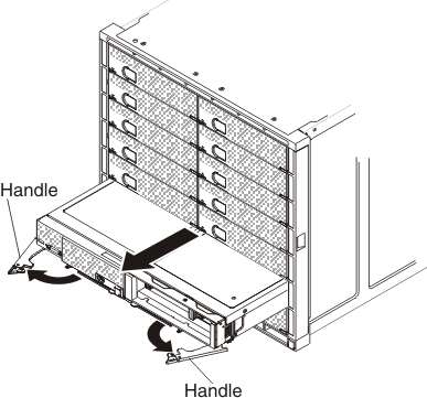
To remove an attached PCIe Expansion Node from a Flex System Enterprise Chassis, complete the following steps.

  1. If there are cables connected to the optional devices that are installed in the PCIe Expansion Node, disconnect them.
  2. Open the handles on the compute node and the PCIe Expansion Node as shown in the following illustration.

    Graphic illustrating the removal of an attached PCIe Expansion Node from a Flex System Enterprise Chassis
    Attention: To maintain proper system cooling, do not operate the Flex System Enterprise Chassis without a compute node or filler installed in each bay.
  3. Pull the 2-bay shelf with the attached compute node and the PCIe Expansion Node out of the bay and place the assembly on a flat static-protective surface with the right side of the assembly oriented toward you.
  4. Install either a 1-bay shelf with fillers or another compute node within 1 minute.
  5. Remove the PCIe Expansion Node cover. See Removing the cover for instructions.
  6. Remove the PCIe Expansion Node I/O expansion adapters, if installed. See Removing an I/O expansion adapter for instructions.
  7. Disconnect the interposer cable from the system board connector. See Removing the interposer cable for instructions.
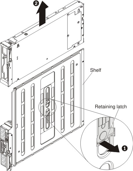
  8. Lift the right side of the assembly up and stand the assembly on it's left side with the bottom of the 2-bay shelf oriented towards you.

    Graphic illustrating the removal of an attached PCIe Expansion Node from a 2-bay shelf
  9. On the bottom of the 2-bay shelf, pull out on the retaining latch to release the PCIe Expansion Node and simultaneously slide the unit up to disengage the alignment posts; then, lower the assembly back to the work surface and lift the PCIe Expansion Node off the shelf.