Use these instructions to install a replacement expansion shelf on the storage expansion node assembly.
Before you install the expansion shelf, read Safety and Installation guidelines.
Attention:Before you connect a compute node to the storage expansion node, you must make sure that the integrated management module II (IMM2) primary and backup firmware in the compute node is at level ibm_fw_imm2_1aoo34x-1.xx_anyos_noarch or later. If the IMM2 firmware in the compute node is at an earlier level when you connect the compute node to the storage expansion node, the firmware in the storage expansion node will become corrupted and unrecoverable, and you will have to replace the storage expansion node. For information about updating the firmware in the compute node, see the compute node Installation and Service Guide.
To install the expansion shelf, complete the following steps:
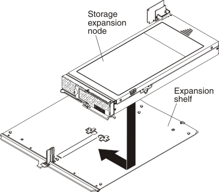
- With the left edge of the storage expansion node aligned
with the expansion node alignment mark on the expansion shelf, orient
the slots on the bottom of the storage expansion node with
the posts on the right side of the expansion shelf. Then, slide the storage expansion node toward
the center of the shelf until the retention latch clicks into place,
as shown in the following illustration.
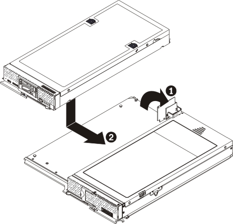
- With the right edge of the compute node aligned with the
compute node alignment mark on the expansion shelf, orient the slots
on the bottom of the compute node with the posts on the left side
of the expansion shelf. Then, slide the compute node toward the center
of the shelf until the retention latch clicks into place, as shown
in the following illustration.
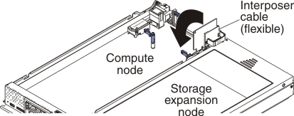
- Connect the interposer cable to the interposer connector
on the compute node system board, as shown in the following illustration.
After you install the expansion shelf, install the storage expansion node assembly into the chassis. See Installing the storage expansion node in an Flex System Enterprise Chassis for instructions.