Use this information to remove a microprocessor and heat sink.
Note: This procedure should be performed only by trained service
technicians.
Before you remove the microprocessor and heat
sink, complete the following steps:
- Read Safety and Installation guidelines.
- If the compute node is installed in a chassis, remove it (see Removing a compute node from a chassis for instructions).
- Carefully lay the compute node on a flat, static-protective surface, orienting the compute node with the bezel pointing toward you.
The following notes describe information that you must
consider when you remove a microprocessor:
- Each microprocessor socket must always contain a heat-sink filler or a microprocessor and heat sink. If the compute node has only one microprocessor, it must be installed in microprocessor socket 1.
- Do not install the microprocessor socket dust cover, if it is available, when removing a microprocessor.
- The microprocessor installation tool might become worn after several uses. Make sure that the tool can hold the microprocessor securely if you are reusing an existing microprocessor installation tool. Do not return the tool with other parts that you are returning.
- If you are installing a second microprocessor, the option kit comes with a microprocessor installation tool that you must use when you install a microprocessor. The microprocessor installation tool comes with the replacement microprocessor installed on it and a cover over the microprocessor.
- If you are replacing a defective microprocessor, the CRU kit comes with one installation tool with the replacement microprocessor installed on it and a cover over the microprocessor, and one empty installation tool without a cover.
- If you are replacing a defective microprocessor, you must obtain
the following for use during the replacement procedure (see Parts listing, Types 9532 and 2951).
- Alcohol wipes
- Thermal grease
Attention:
- Remove and install only one microprocessor at a time. When removing or installing a microprocessor, protect the other microprocessor socket with a microprocessor heat sink filler.
- Always use the microprocessor installation tool to remove or install a microprocessor. Failure to use the microprocessor installation tool can damage the microprocessor sockets on the system board. Any damage to the microprocessor sockets might require replacing the system board.
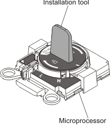
Note: Be sure to use the installation tool that comes
with your microprocessor. The installation tool has two settings for
installing two different sizes of microprocessors. The settings that
are marked on the tool are
Lfor smaller low core microprocessors, and
Hfor larger high core microprocessors. The tool automatically adjusts during use to the correct setting for your microprocessor.
To remove a microprocessor and heat sink, complete the following steps.
-
Open the microprocessor socket release levers
and retainer.
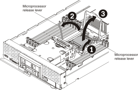
- Identify which release lever is labeled as the first release lever to open (labeled on the microprocessor-retention assembly) and open it.
- Open the second release lever on the microprocessor socket.
- Open the microprocessor retainer.
Attention:- Dropping the microprocessor during installation or removal can damage the contacts.
- Do not touch the connectors on the microprocessor and the microprocessor socket; handle the microprocessor by the edges only. Contaminants on the microprocessor contacts, such as oil from your skin, can cause connection failures between the contacts and the socket.
-
Using the microprocessor installation tool,
remove the microprocessor from the socket.
-
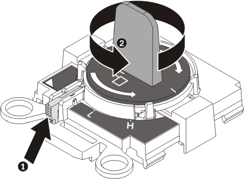
Select the empty installation tool and make sure that
the handle is in the open position.
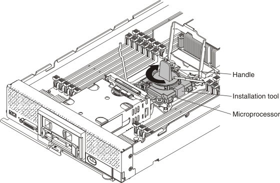
If the installation tool handle is not in the open position: 1) lift the interlock latch and hold it up while you 2) twist the microprocessor installation tool handle counterclockwise to the open position, and then release the interlock latch. The following illustration of the installation tool shows the location of the interlock latch and counterclockwise rotation of the handle before loading the microprocessor.
-
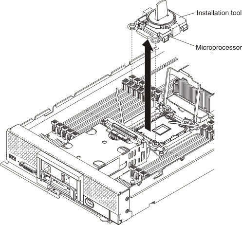
Align the installation tool with the screws, as shown
in the following graphic, and lower the installation tool on the microprocessor.
The installation tool rests flush on the socket only when it is aligned
correctly.
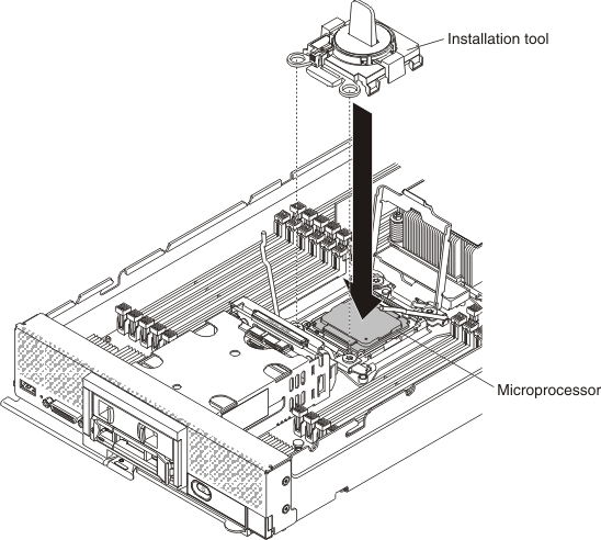
-
Gently twist the handle of the installation tool clockwise
until it locks in the
H
orL
position, depending on the size of microprocessor; then, lift the microprocessor out of the socket.
-
Select the empty installation tool and make sure that
the handle is in the open position.
If you are instructed to return the microprocessor and heat
sink, follow all packaging instructions, and use any packaging materials
for shipping that are supplied to you.