Use this information to install a microprocessor and heat sink.
Note: This procedure should be performed only by trained service
technicians.
Before you install a microprocessor and heat
sink, complete the following steps:
- Read Safety and Installation guidelines.
- If the compute node is installed in a chassis, remove it (see Removing a compute node from a chassis for instructions).
- Carefully lay the compute node on a flat, static-protective surface, orienting the compute node with the bezel pointing toward you.
The following notes describe the type of microprocessor
that the compute node supports and other information that you must
consider when you install a microprocessor:
- This component can be installed as an optional device or as a CRU. The installation procedure is the same for the optional device and the CRU.
- The optional microprocessors that Lenovo supports are limited by the capacity and capability of the compute node. Any microprocessors that you install must have the same specifications as the microprocessors that came with the compute node.
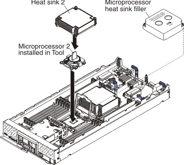
- Each microprocessor socket must always contain a heat-sink filler or a microprocessor and heat sink. If the compute node has only one microprocessor, it must be installed in microprocessor socket 1.
- If you are installing a second microprocessor, make sure that the microprocessors are identical.
- Before you install a new microprocessor, download and install the most current level of UEFI code (see Updating firmware and device drivers).
- When you install a second microprocessor, you might have to install additional memory or redistribute memory across the DIMM connectors (see Installing a DIMM).
- Installing microprocessor 2 enables DIMM connectors 13 through 24 and the expansion connector (see System-board connectors). Microprocessor 2 is also required by some optional devices, such as PCIe hard disk drives, that can be installed in the compute node (see documentation that comes with the optional device for additional information and requirements).
- The microprocessor installation tool might become worn after several uses. Make sure that the tool can hold the microprocessor securely if you are reusing an existing microprocessor installation tool. Do not return the tool with other parts that you are returning.
- If you are installing a second microprocessor, the microprocessor option kit comes with a microprocessor installation tool that you must use when you install a microprocessor. The microprocessor installation tool comes with the replacement microprocessor installed on it and a cover over the microprocessor.
- If you are replacing a defective microprocessor, the CRU kit comes with one installation tool with the replacement microprocessor installed on it and a cover over the microprocessor, and one empty installation tool without a cover.
- If you are replacing a defective microprocessor, you must obtain
the following for use during the replacement procedure (see Parts listing, Types 9532 and 2951).
- Alcohol wipes
- Thermal grease
Attention:
- Remove and install only one microprocessor at a time. When removing or installing a microprocessor, protect the other microprocessor socket with a microprocessor heat sink filler.
- Always use the microprocessor installation tool to remove or install a microprocessor. Failure to use the microprocessor installation tool can damage the microprocessor sockets on the system board. Any damage to the microprocessor sockets might require replacing the system board.
- Different microprocessor types might require a different type of heat sink. To maintain adequate cooling, make sure that you install the heat sink type specified for your microprocessor.
- Thermal grease can stay functional on the heat sink for two years. When installing a new heat sink, make sure to check the manufacturing date to ensure the thermal grease is still functioning. If the date is over two years ago, replace the thermal grease to avoid seating issues.
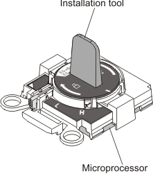
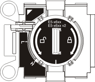
Note: Be sure to use the installation
tool that comes with your microprocessor. The installation tool has
two settings for installing two different sizes of microprocessors.
The settings that are marked on the tool are
Lfor smaller low core microprocessors, and
Hfor larger high core microprocessors. The tool automatically adjusts during use to the correct setting for your microprocessor.
To install a microprocessor and heat sink, complete the following steps.
-
Open the microprocessor socket release levers and retainer.
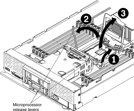
- Identify which release lever is labeled as the first release lever to open (labeled on the microprocessor-retention assembly) and open it.
- Open the second release lever on the microprocessor socket.
- Open the microprocessor retainer.
-
Install the microprocessor in the microprocessor socket.
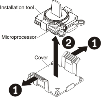
-
Release the sides of the cover and remove the cover
from the installation tool. The microprocessor is preinstalled on
the installation tool.
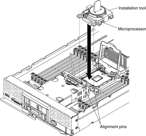
-
Align the installation tool with the microprocessor
socket. The installation tool rests flush on the socket only if it
is properly aligned.
-
Twist the handle of the installation tool assembly counterclockwise
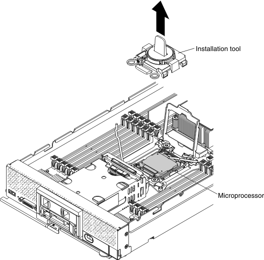
until the microprocessor is inserted into the socket, and lift the
installation tool out of the socket.
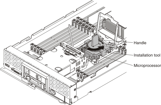
The following illustration shows the installation tool handle in the open position, ready for tool removal.
The following illustration shows removing the installation tool handle.
Attention:- Do not press the microprocessor into the socket.
- Do not touch the thermal grease on the bottom of the heat sink or on top of the microprocessor. Touching the thermal grease will contaminate it. If the thermal material becomes contaminated, see Thermal grease
-
Remove the microprocessor protective dust cover, tape,
or label from the surface of the microprocessor socket, if one is
present.
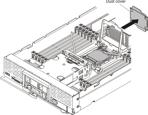
Attention:- Make sure that the microprocessor is aligned correctly in the socket before you try to close the microprocessor retainer.
- Make sure that the dust cover is removed before you try to close the microprocessor retainer.
-
Release the sides of the cover and remove the cover
from the installation tool. The microprocessor is preinstalled on
the installation tool.
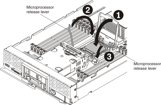
-
Close the microprocessor socket release retainer and levers.
After you install a microprocessor and heat sink, complete
the following steps:
- Install the cover (see Installing the compute node cover).
- Install the compute node in a Lenovo Flex System chassis (see Installing a compute node in a chassis for instructions).