Use this information to install the light path diagnostics panel.
Before you begin
- Read Safety and Installation guidelines.
- If the compute node is installed in an Flex System chassis, remove it (see Removing a compute node from a chassis for instructions).
- Carefully lay the compute node on a flat, static-protective surface, orienting the compute node with the bezel pointing toward you.
Procedure
To install a light path diagnostics panel, complete the following steps.
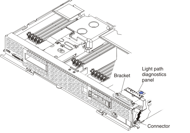
- Remove the cover (see Removing the compute node cover).
- Connect the cable on the system board.
- Align the light path diagnostics panel with the bracket.
- Press the light path diagnostics panel securely in the bracket.
What to do next
- Install the cover onto the compute node (see Installing the compute node cover for instructions).
- Install the compute node into the chassis (see Installing a compute node in a chassis for instructions).