Use this information to install a microprocessor and heat sink. Microprocessors are installed in both the upper and lower compute nodes.
Note: This procedure should be performed only by trained service
technicians.
Before you install a microprocessor and heat
sink, complete the following steps:
- Read Safety and Installation guidelines.
- If the Flex System x222 Compute Node is installed in a chassis, remove it (see Removing a compute node from a chassis for instructions).
- Carefully lay the compute node on a flat, static-protective surface, orienting the compute node with the bezel pointing toward the left.
The following notes describe the type of microprocessor
that the compute node supports and other information that you must
consider when you install a microprocessor:
- This component can be installed as an optional device or as a CRU. The installation procedure is the same for the optional device and the CRU.
- The optional microprocessors are limited by the capacity and capability of the compute node. Any microprocessors that you install must have the same specifications as the microprocessors that came with the compute node.
- Each microprocessor socket must always contain a socket cover and heat-sink filler or a microprocessor and heat sink. If the compute node has only one microprocessor, it must be installed in microprocessor socket 1.
- If you are installing a second microprocessor, make sure that the microprocessors are identical.
- Before you install a new microprocessor, download and install the most current level of UEFI code (see Updating firmware and device drivers).
- When you install a second microprocessor, you might have to install additional memory or redistribute memory across the DIMM connectors. See Installing a DIMM.
- The microprocessor installation tool might become worn after several uses. Make sure that the tool can hold the microprocessor securely if you are reusing an existing microprocessor installation tool. Do not return the tool with other parts that you are returning.
- If you are installing a second microprocessor, the microprocessor option kit comes with a microprocessor installation tool that you must use when you install a microprocessor. The microprocessor installation tool comes with the replacement microprocessor installed on it and a cover over the microprocessor.
- If you are replacing a defective microprocessor, the CRU kit comes with one installation tool with the replacement microprocessor installed on it and a cover over the microprocessor, and one empty installation tool without a cover.
- If you are replacing a defective microprocessor, you must obtain
the following for use during the replacement procedure (see Parts listing, Types 7916 and 2589).
- Alcohol wipes
- Thermal grease
Attention:
- Do not use any tools or sharp objects to lift the locking levers on the microprocessor socket. Doing so might result in permanent damage to the system board.
- Do not touch the contacts in the microprocessor socket. Touching these contacts might result in permanent damage to the system board.
To install a microprocessor and heat sink, complete the following steps.
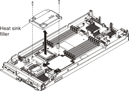
- Remove the heat-sink filler, if one is
present.
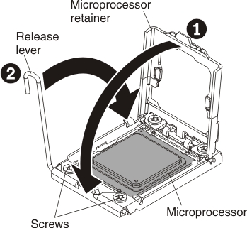
- Open the microprocessor socket release lever
and retainer.
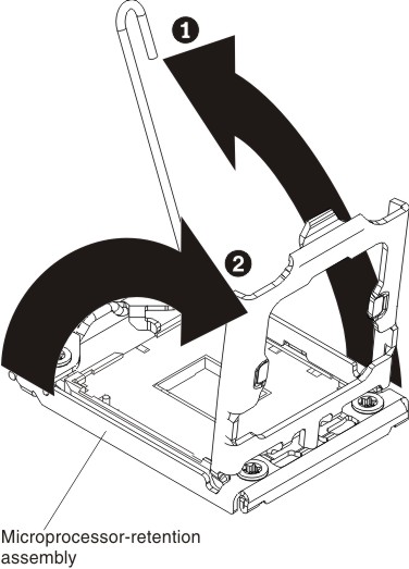
- Open the release lever on the microprocessor socket.
- Open the microprocessor retainer on the microprocessor socket.
- Install the microprocessor on the microprocessor socket:
- Release the sides of the cover and remove the cover
from the installation tool. The microprocessor is preinstalled on
the installation tool.
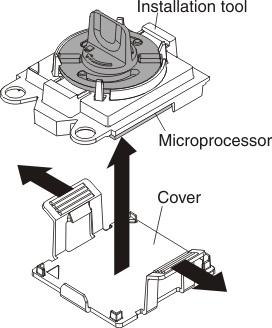 Note: Do not touch the microprocessor contacts. Contaminants on the microprocessor contacts, such as oil from your skin, can cause connection failures between the contacts and the socket.
 - Align the installation tool with the microprocessor
socket. The installation tool rests flush on the socket only if it
is properly aligned.
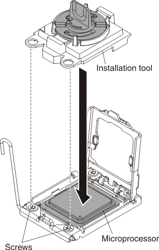
- Release the sides of the cover and remove the cover
from the installation tool. The microprocessor is preinstalled on
the installation tool.
- Close the microprocessor socket release retainer
and lever.
 Attention:
- If you are installing a new heat sink, do not set down the heat sink after you remove the plastic cover.
- Do not touch the thermal material on the bottom of the heat sink. Touching the thermal material will contaminate it.
- If you are installing a new heat sink, remove
the plastic protective cover from the bottom of the heat sink. If
you are reinstalling a heat sink that you previously removed from
the compute node, make sure that the thermal material is still on
the bottom of the heat sink and on the top of the microprocessor.
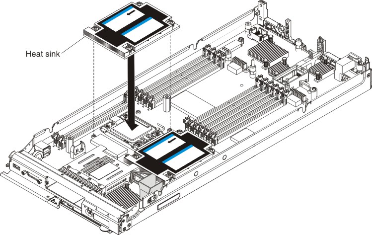
Attention: Attempting to install the heat sink in an orientation other than described in this step might result in damage to the system board, microprocessor, or heat sink.- Position the heat sink over the microprocessor, orienting the heat sink edge that has the most fins facing toward the compute node bezel. If the heat sink is correctly oriented, the start arrow on the heat sink label will point toward the compute node bezel.
- Align and place the heat sink on top of the microprocessor in the retention bracket, thermal material side down.
- Press firmly on the heat sink.
- Align the screws on the heat sink with the holes on the heat-sink retention module.
- Press firmly on the captive screws and tighten them using a P1 Phillips screwdriver, alternating among the screws using a figure-eight pattern. For the first turn of each screw, rotate it one full rotation; then, tighten each screw two to three rotations until they are tight. Do not overtighten the screws by using excessive force. If you are using a torque wrench, tighten the screws to 8 inch-pounds (in-lb) to 10 in-lb (0.9 Newton-meters (Nm) to 1.13 Nm). Refer to the label on the heat sink for more information.
After you install a microprocessor and heat sink, complete
the following steps:
- Install the upper compute node (see Installing the upper compute node).
- Install the Flex System x222 Compute Node in a Flex System chassis (see Installing a compute node in a chassis for instructions).