Use this information to install a Flex System x222 Compute Node in
a Flex System chassis.
Before you install the
Flex System x222 Compute Node in
a chassis, read
Safety and
Installation guidelines.
Statement
21

CAUTION:
Hazardous energy is
present when the compute node is connected to the power source. Always
replace the compute node cover before installing the compute node.
Note:
- The upper compute node acts as the cover for the Flex System x222 Compute Node.
You can not install the Flex System x222 Compute Node in
a chassis unless the upper compute node is installed.
- Although the upper and lower compute nodes are configured and
operated independently, they must be installed together as a complete Flex System x222 Compute Node unit.
If you are using Flex System Manager management software to
manage an operating system, you must have either an integrated Ethernet
controller or a network interface adapter for management network communication.
For a list of supported optional devices for the Flex System x222 Compute Node,
see the Lenovo ServerProven website.
To install the Flex System x222 Compute Node in
a chassis, complete the following steps.
- Select the node bay.
Note:
- If you are reinstalling a Flex System x222 Compute Node that
you removed, you must install it in the same node bay from which you
removed it. Some compute node configuration information and update
options are established according to node bay number. Reinstalling
a Flex System x222 Compute Node into
a different node bay can have unintended consequences. If you reinstall
the Flex System x222 Compute Node into
a different node bay, you might have to reconfigure the upper and
lower compute nodes.
- To maintain proper system cooling, do not operate the Flex System chassis
without a compute node, or node bay filler in each node bay.
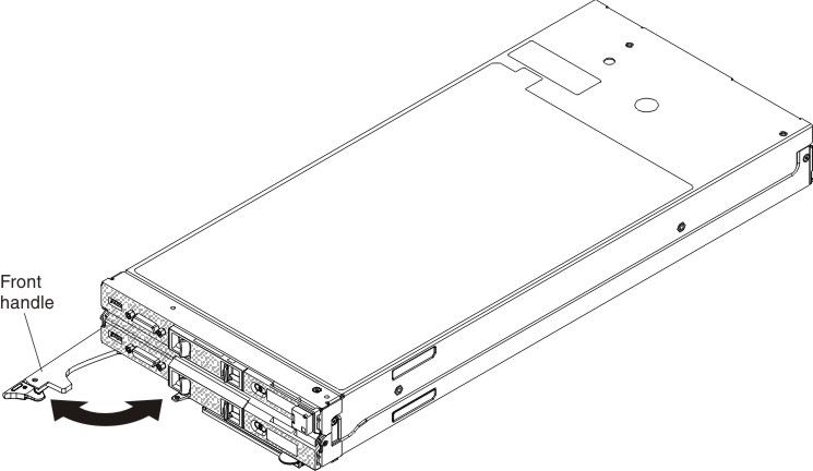
- Make sure that the front handle on the Flex System x222 Compute Node is
in the open position.
- Slide the Flex System x222 Compute Node into
the node bay until it stops.
- Push the front handle on the front of the Flex System x222 Compute Node to
the closed position.
Note: After the Flex System x222 Compute Node is
installed, the IMM2s in the upper and lower compute nodes initialize
and synchronize with the Chassis Management Module. This process takes
approximately 90 seconds to complete. The power LED on each compute
node flashes rapidly while the compute node is initializing, and the
power button on each compute node does not respond until this process
is complete. After initialization, the power LED on each compute node
flashes slowly (approximately once per second). Once the power LED
is flashing slowly, you can press the power button to turn on the
compute node.
- Turn on the upper and lower compute nodes (see Turning on a compute node for instructions).
- Make sure that the power LED on each compute node control
panel is lit continuously, indicating that the compute node is receiving
power and is turned on.
- If you have other compute nodes to install, do so now.
- You can place identifying information on the label tabs
that are accessible from the front of the compute node.
If this is the initial installation of the Flex System x222 Compute Node in
the chassis, you must configure the upper and lower compute nodes
through the Setup utility and install the compute node operating systems.
See Updating a compute node configuration and Installing the operating system for details.
If
you have changed the configuration of the upper or lower compute node
or if you are installing a different Flex System x222 Compute Node from
the one that you removed, you must configure the upper and lower compute
nodes through the Setup utility, and you might have to install the
compute node operating systems (see Using the Setup utility).
The upper and lower compute nodes are configured independently.