Use this information to locate the system-board jumpers.
The following illustration shows the locations of the jumpers on the system board.
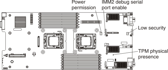
The following table describes the function of each jumper on the system board.
| Jumper name | Description |
|---|---|
| IMM2 debug serial port enable (CN42) | Two-pin header. If a jumper is installed, the serial I/O port is sent to the IMM2. If a jumper is not installed, the serial I/O port is sent to the front serial port. |
| Low security (CN45) | Three-pin jumper block for debug only. The default position are pins 2 and 3. |
| Power permission (CN47) | Two-pin jumper block. The default is no jumper. Place a jumper on pins 1 and 2 to force power permission from the IMM2 to the real time management module (RTMM). |
| Trusted Platform Module (TPM) physical presence (CN51) | Two-pin jumper. The default is no jumper. Place a jumper on pins 1 and 2 to indicate a physical presence to the IMM2 TPM chip. |