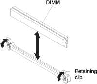
Use this information to remove a dual inline memory module (DIMM).
Before you remove a DIMM, complete the following steps:
- Read Safety and Installation guidelines.
- If the compute node is installed in an Flex System chassis, remove it (see Removing a compute node from a chassis for instructions).
- Carefully lay the compute node on a flat, static-protective surface, orienting the compute node with the bezel pointing toward you.
After you install or remove a DIMM, you must change and save
the new configuration information by using the Setup utility. When
you turn on the compute node, a message indicates that the memory
configuration has changed. Start the Setup utility and select Save
Settings (see Using the Setup utility for
more information) to save changes.
To remove a DIMM, complete the following steps.
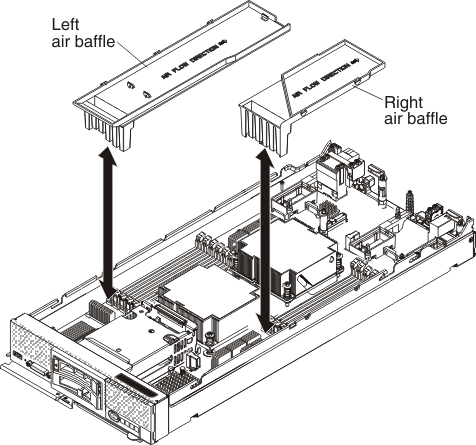
- Remove the air baffle installed over the DIMM connector.
If you are instructed to return the DIMM, follow all packaging instructions, and use any packaging materials for shipping that are supplied to you.