Use this information to locate the system-board jumpers.
The following illustration shows the locations of the jumpers on the system board.
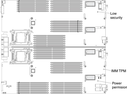
The following table describes the function of each jumper on the system board.
| Jumper number | Description |
|---|---|
| IMM TPM (JP2461) | Two-pin jumper. The default is no jumper. Place a jumper on pins 1 and 2 to indicate a physical presence to the IMM2 TPM chip. |
| Low Security (J2101) | Three-pin jumper block. The default position is pins 2 and 3. |
| Power permission (JP9601) | Two-pin jumper block. The default is no jumper. Place a jumper on pins 1 and 2 to force power permission from the IMM2 to the real time management module (RTMM). |