(Trained service technician only) Use these instructions to install the chassis shuttle in the Flex System Carrier-Grade chassis.
Important: The power supplies, I/O modules, and CMM that
are installed in the shuttle connect directly to the midplane. Do
not latch these devices in the shuttle before you insert the shuttle;
the chassis is not designed for all of those devices to connect to
the midplane at the same time.
To install the chassis shuttle, complete the following steps.
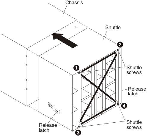
- Align the shuttle with the rear of the chassis and insert the shuttle into the chassis.
- Push the release latches in; then, slide the shuttle into the chassis until it locks in place.
- Tighten the captive screws that you removed earlier with
a T-15 Torx driver:
- Install the left, right, and bottom support brackets on the rear of the chassis, if you removed them.
After you install the shuttle, complete the following steps:
- Reinstall the components that you removed from the rear of the Flex System Carrier-Grade
chassis:
- I/O modules (see Replacing an I/O module).
- CMM (see Replacing a Chassis Management Module).
- Fan modules (see Replacing a 40 mm fan module and Replacing a 80 mm fan module).
- Power supplies (see Replacing a power supply).
- Connect any cables that you disconnected from the modules in the rear of the chassis.
- Connect the chassis to power (see Connecting the chassis to power).
- Restart any compute nodes that you shut down. See the documentation that comes with each compute node for detailed instructions.