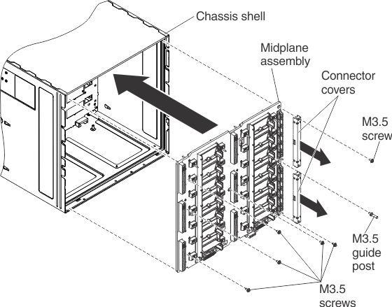
(Trained service technician only) Use these instructions to install the midplane in the Flex System Carrier-Grade chassis.
To install the midplane, complete the following steps.

Important: After you install
a new midplane, you must install and program the rear LED card that
comes with the new midplane, and program the vital product data (VPD)
(see Replacing the rear LED card for instructions), so that Lenovo XClarity Administrator can
use the same UUID for the chassis afterwards.
After the new
rear LED card is installed, reassemble the chassis and program the
vital product data (VPD) that is stored on the card. Complete the
following steps:- Reinstall the shuttle into the chassis (see Replacing the shuttle).
- Reinstall all of the components and component bay fillers that
you removed from the rear of the chassis. See the following tasks
for additional instructions:
- Replacing a power supply
- Replacing a fan logic module
- Replacing a 80 mm fan module
- Replacing a 40 mm fan module
- Replacing a Chassis Management Module
- Reinstall the I/O modules in the I/O bays but do not close the I/O module release handles. See Replacing an I/O module.
- Connect any cables that you disconnected from the modules in the rear of the chassis.
- Connect the chassis to power (see Connecting the chassis to power).
- Log in to the CMM and
access the command-line interface (CLI). You can access the CMM CLI
through a direct serial or Ethernet connection to the CMM,
through a Telnet connection to the IP address of the CMM,
or through a Secure Shell (SSH) connection to the CMM.
You must authenticate with the CMM before
issuing commands. Use the CLI vpdrep command to program the
serial number, machine type model, and the universal unique identifier
(UUID) into the replacement rear LED card. The CLI command to program
this data can be executed in two ways, the data for the three command
arguments can be entered individually or together in any combination.
At least one command argument must be present. For example, to program
all three fields at once: vpdrep -sn -tm -uuid where:
vpdrep command arguments Description -sn Chassis serial number (7 alphanumeric characters) -tm Machine type model (7 alphanumeric characters) -uuid Universally unique identifier (32 hex digits, spaces not allowed) - Restart the CMM for the vital product data change to take effect. The vital product data values can be queried by using the CLI info command.
- Close the release handles on the compute nodes and I/O modules in order to seat the nodes and I/O modules in the midplane connectors.
- Restart any compute nodes that you shut down. See the documentation that comes with the compute node for detailed instructions.
- The I/O Modules are powered-on automatically by the CMM.