Use this information to locate the system-board switches.
The following illustration shows the location of the switch blocks on the system board.
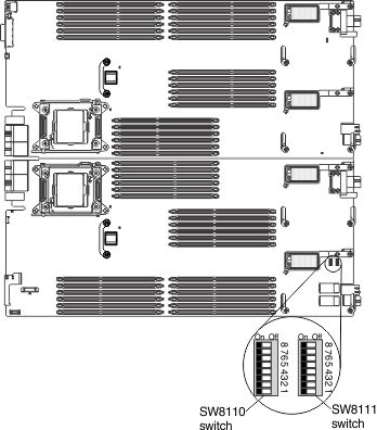
The following table describes the functions of the switches.
| Switch number | Description | Switch setting | Definition |
|---|---|---|---|
| SW8110-1 | Password override | The default position is off. | Changing this switch to the on position overrides the power-on password. |
| SW8110-2 | UEFI TPM | The default position is off. | Changing this switch to the on position indicates a physical presence to the TPM. |
| SW8110-3 | Real time clock (RTC) reset | The default position is off. | Changing this switch to the on position resets the RTC. A momentary toggle is all that is required. To avoid excessive CMOS battery drain, do not leave this switch in the on position. |
| SW8110-4 | Boot backup IMM2 | The default position is off. | When the switch is in the default off position, the compute node will boot by using the primary IMM2 firmware. When the switch is in the on position, the compute node will boot by using a backup of the IMM2 firmware. |
| SW8110-5 | Boot backup UEFI | The default position is off. | Changing this switch to the on position forces the compute node to boot from the backup UEFI image. |
| SW8110-6 | IMM force update | The default position is off. | Changing this switch to the on position
bypasses the operational firmware image and performs a IMM firmware
update, if the normal firmware update procedure results in an inoperative
IMM. Note: Use this switch only if the normal firmware update procedure
fails and the operational firmware image is corrupted. Use of this
switch disables normal baseboard management controller operation.
|
| SW8110-7 | IMM SPI ROM Chip Select | The default position is off. | Changing this switch to the on position forces the compute node to select system SPI ROM0 or ROM1. |
| SW8110-8 | Real time management module (RTMM) flash bypass | The default position is off. | Changing this switch to the on position forces the compute node to use RTMM ROM instead of flash. |
| SW8111-1 | Reset FPGA Configuration Logic | The default position is off. | Changing this switch to the on position forces the compute node to reset the FPGA configuration logic. |
| SW8111-2 | IMMv2 Reset | The default position is off. | Changing this switch to the on position forces the compute node to reset the IMM. |
| SW8111-3 | ME Flash descriptor security override | The default position is off. | Changing this switch to the on position forces the compute node to override security in the flash descriptor. |
| SW8111-4 | Boot Backup ME | The default position is off. | Changing this switch to the on position forces the compute node to boot from the backup ME. |
| SW8111-5, SW8111-6 | Selecting dongle serial port MUX (U9812) | on, on off, on on, off off, off | LOM TX/RX RTMM TX/RX IMM TX/RX SIO TX/RX |
| SW8111-7, SW8111-8 | Selecting dongle serial port MUX (U9811) | on, on off, on on, off off, off | SAS TX/RX FPGA TX/RX IMM TX/RX SIO RTS/CTS |