Use this information to remove the solid state drive cage and backplane.
Before you remove the solid state drive cage and backplane,
complete the following steps:
- Read Safety and Installation guidelines.
- If the compute node is installed in a Lenovo Flex System chassis, remove it (see Removing a compute node from a chassis for instructions).
- Carefully lay the compute node on a flat, static-protective surface, orienting the compute node with the bezel pointing toward you.
The solid state drive cage and backplane are available in
the optional Flex System flash kit.
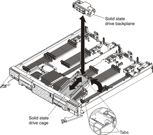
To remove the solid state drive cage and backplane, complete the following steps.
- Remove the cover (see Removing the compute node cover).
- Remove the solid state drive bezel.
- Remove the solid state drives (see Removing a solid state drive).
- Pull the solid state drive backplane from the cage.
- Remove the solid state drive mounting sleeve (see Removing the solid state drive mounting sleeve).
- Lift up on the rear of the cage to disconnect it from the connector on the system board.
- Remove the cage from the compute node at an angle.
If you are instructed to return the solid state drive cage
and backplane, follow all packaging instructions, and use any packaging
materials for shipping that are supplied to you.