Use this information to install an interposer cable.
Before you install an interposer cable,
complete the following steps:
- Read Safety and Installation guidelines.
- If the compute node is installed in a chassis, remove it (see Removing a compute node from a chassis for instructions).
- Carefully lay the compute node on a flat, static-protective surface, orienting the compute node with the bezel pointing toward you.
This component can be installed as an optional device or as a CRU. The installation procedure is the same for the optional device and the CRU.
Two microprocessors must be installed for the compute node to support an interposer cable.
To install an interposer cable, complete the following steps:
- Remove the cover (see Removing the compute node cover).
- Locate the interposer connector (see System-board connectors).
- If an I/O expansion adapter is installed over the interposer connector, remove it (see Removing an I/O expansion adapter).
- Touch the static-protective package that contains the interposer cable to any unpainted metal surface on the Flex System chassis or any unpainted metal surface on any other grounded rack component; then, remove the interposer cable from the package.
- Remove the plastic cover from the connector, if one is present.
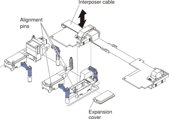
- Orient the connector on the interposer cable with the connector and alignment pins on the system board; then, press the cable into the interposer connector.
- Firmly press on the indicated locations to seat the interposer cable.
- If necessary, install the I/O expansion adapter (see Installing an I/O expansion adapter).
After you install the interposer cable,
complete the following steps:
- See the documentation that comes with the optional device that attaches to the interposer cable to complete the installation.
- Install the cover onto the compute node (see Installing the compute node cover for instructions).