Use this information to install a DIMM.
- Read Safety and Installation guidelines.
- Read the documentation that comes with the DIMMs.
- If the compute node is installed in a chassis, remove it (see Removing a compute node from a chassis for instructions).
- Carefully lay the compute node on a flat, static-protective surface, orienting the compute node with the bezel pointing toward you.
This component can be installed as an optional device or as a CRU. The installation procedure is the same for the optional device and the CRU.
After you install or remove a DIMM, you must change and save the new configuration information by using the Setup utility. When you turn on the compute node, a message indicates that the memory configuration has changed. Start the Setup utility and select Save Settings (see Using the Setup utility for more information) to save changes.
- Verify that the amount of installed memory is the expected amount
of memory through the operating system, by watching the monitor as
the compute node starts, by using the CMM sol command,
or through the management node (if available).
- For more information about the CMM sol command, see the "Flex System Chassis Management Module: Command-Line Interface Reference Guide".
- For more information about Lenovo XClarity Administrator, see the Lenovo XClarity Administrator information page.
- For more information about Flex System Manager management software, see "Flex System Manager Software: Installation and Service Guide".
- Run the Setup utility to reenable the DIMMs (see Using the Setup utility for more information).
The compute node has a total of 24 dual inline memory module (DIMM) connectors. The compute node supports low-profile (LP) DDR3 DIMMs with error-correcting code (ECC) in 2 GB, 4 GB, 8 GB, 16 GB, and 32 GB capacities.
The following illustration shows the system-board components, including the DIMM connectors.
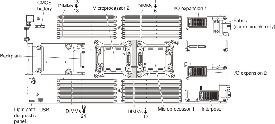
The memory is accessed internally through four channels. Each memory channel has three DIMM connectors for each microprocessor (six total). Each channel can have a maximum of eight ranks. The following table lists the memory channels and shows which DIMM connectors are in the channel for each microprocessor.
| Microprocessor | Memory channel | DIMM connectors |
|---|---|---|
| Microprocessor 1 | Channel A | 4, 5, and 6 |
| Channel B | 1, 2, and 3 | |
| Channel C | 7, 8, and 9 | |
| Channel D | 10, 11, and 12 | |
| Microprocessor 2 | Channel A | 22, 23, and 24 |
| Channel B | 19, 20, and 21 | |
| Channel C | 13, 14, and 15 | |
| Channel D | 16, 17, and 18 |
Depending on the memory mode that is set in the Setup utility, the compute node can support a minimum of 2 GB and a maximum of 384 GB of system memory in a compute node with one microprocessor. If two microprocessors are installed, the compute node can support a minimum of 4 GB and a maximum of 768 GB of system memory.
- Maximum DIMM capacity:
- Registered DIMMs (RDIMMs): 384 GB (using 16 GB RDIMMs)
- Unbuffered DIMMs (UDIMMs): 128 GB (using 8 GB UDIMMs)
- Load Reduced DIMMs (LRDIMMs): 768 GB (using 32 GB LRDIMMs)
- RDIMM sizes supported (GB): 2, 4, 8, 16, 32
- UDIMM sizes supported (GB): 2, 4, 8
- LRDIMM sizes supported (GB): 16, 32
- You cannot mix UDIMMs, RDIMMs and LRDIMMs in the same compute node.
- A total of eight ranks on each channel is supported.
- If a quad-rank DIMM is installed, install it in the connector at the end of the memory channel.
- If a channel has one or more quad-rank DIMMs, only two DIMMs per channel is supported.
- If you install LRDIMMs in a 3 DIMM per channel configuration, performance might be reduced compared to standard DIMMs.
- Independent-channel mode: Independent-channel mode provides a maximum of 384 GB of usable memory with one installed microprocessor, and 768 GB of usable memory with two installed microprocessors (using 32 GB DIMMs).
- Rank-sparing mode: In rank-sparing mode, one memory DIMM
rank serves as a spare of the other ranks on the same channel. The
spare rank is held in reserve and is not used as active memory. The
spare rank must have identical or larger memory capacity than all
the other active DIMM ranks on the same channel. After an error threshold
is surpassed, the contents of that rank is copied to the spare rank.
The failed rank of DIMMs is taken offline, and the spare rank is put
online and used as active memory in place of the failed rank. The following notes describe additional information that you must consider when you select rank-sparing memory mode:
- Rank-sparing on one channel is independent of the sparing on all other channels.
- You can use the Setup utility to determine the status of the DIMM ranks.
- Mirrored-channel mode: In mirrored-channel mode, memory is installed in pairs. Each DIMM in a pair must be identical in size and architecture. The channels are grouped in pairs with each channel receiving the same data. One channel is used as a backup of the other, which provides redundancy. The memory contents on channel B are duplicated in channel C, and the memory contents of channel A are duplicated in channel D. The effective memory that is available to the system is only half of what is installed.
One DIMM for each microprocessor is the minimum requirement. However, for optimal performance, install DIMMs in sets of four so that you distribute memory equally across all four channels. If two microprocessors are installed, distribute memory across all channels and equally between the microprocessors.
| Number of installed DIMMs | 1 microprocessor installed | 2 microprocessors installed | ||
|---|---|---|---|---|
| DIMM slot number | DIMMs per channel | DIMM slot number | DIMMs per channel | |
| 1 | 4 | 1 | 4 | 1 |
| 2 | 1 | 24 | ||
| 3 | 9 | 1 | ||
| 4 | 12 | 21 | ||
| 5 | 5 | 2 | 9 | |
| 6 | 2 | 13 | ||
| 7 | 8 | 12 | ||
| 8 | 11 | 16 | ||
| 9 | 6 | 3 | 5 | 2 |
| 10 | 3 | 23 | ||
| 11 | 7 | 2 | ||
| 12 | 10 | 20 | ||
| 13 | Not used - maximum of 12 DIMMs in systems with 1 microprocessor | 8 | ||
| 14 | 14 | |||
| 15 | 11 | |||
| 16 | 17 | |||
| 17 | 6 | 3 | ||
| 18 | 22 | |||
| 19 | 3 | |||
| 20 | 19 | |||
| 21 | 7 | |||
| 22 | 15 | |||
| 23 | 10 | |||
| 24 | 18 | |||
| DIMM pair installation order | 2 DIMMs per channel | 3 DIMMs per channel | ||
|---|---|---|---|---|
| 1 microprocessor installed | 2 microprocessors installed | 1 microprocessor installed | 2 microprocessors installed | |
| 1 | 4 and 5 | 4 and 5 | 4, 5, and 6 | 4, 5, and 6 |
| 2 | 8 and 9 | 20 and 21 | 7, 8, and 9 | 19, 20, and 21 |
| 3 | 1 and 2 | 8 and 9 | 1, 2, and 3 | 7, 8, and 9 |
| 4 | 11 and 12 | 16 and 17 | 10, 11, and 12 | 16, 17 and 18 |
| 5 | n/a | 1 and 2 | n/a | 1, 2, and 3 |
| 6 | 23 and 24 | 22, 23, and 24 | ||
| 7 | 11 and 12 | 10, 11, and 12 | ||
| 8 | 13 and 14 | 13, 14, and 15 | ||
Install DIMMs in order as indicated in the following table for mirrored-channel mode.
| DIMM pair | 1 microprocessor installed | 2 microprocessors installed | ||
|---|---|---|---|---|
| DIMM slot numbers | DIMMs per channel | DIMM slot numbers | DIMMs per channel | |
| 1 | 4 and 11 | 1 | 4 and 11 | 1 |
| 2 | 9 and 121 | 21 and 241 | ||
| 3 | 2 and 51 | 2 | 9 and 121 | |
| 4 | 8 and 111 | 13 and 161 | ||
| 5 | 3 and 61 | 3 | 2 and 51 | 2 |
| 6 | 7 and 101 | 20 and 231 | ||
| 7 | none | 8 and 111 | ||
| 8 | none | 14 and 171 | ||
| 9 | none | 3 and 61 | 3 | |
| 10 | none | 19 and 221 | ||
| 11 | none | 7 and 101 | ||
| 12 | none | 15 and 181 | ||
|
||||
To install a DIMM, complete the following steps:
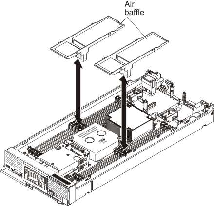
- Remove the air baffle installed over the DIMM connector.
- Touch the static-protective package that contains the DIMM
to any unpainted metal surface on the Flex System chassis
or any unpainted metal surface on any other grounded rack component
in the rack in which you are installing the DIMM for at least 2 seconds;
then, remove the DIMM from its package.
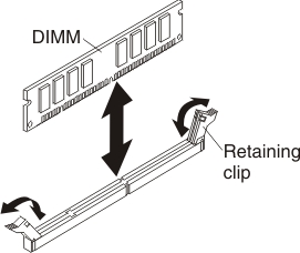
- Make sure that the small tabs on the retaining clips engage
the notches on the DIMM. If there is a gap between the DIMM and the
retaining clips, the DIMM has not been correctly installed. Press
the DIMM firmly into the connector, and then press the retaining
clips toward the DIMM until the tabs are fully seated. When the DIMM
is correctly installed, the retaining clips are parallel to the sides
of the DIMM.
- Install the cover onto the compute node (see Installing the compute node cover for instructions).
- Install the compute node into the chassis (see Installing a compute node in a chassis for instructions).