To add, edit, and remove a boot target, chassis, and vNIC template, complete the following steps.
Procedure
-
Select Templates. The summary view shows information
about the templates. You can also select a line to view detailed information.
-
Select a template from the following choices.
-
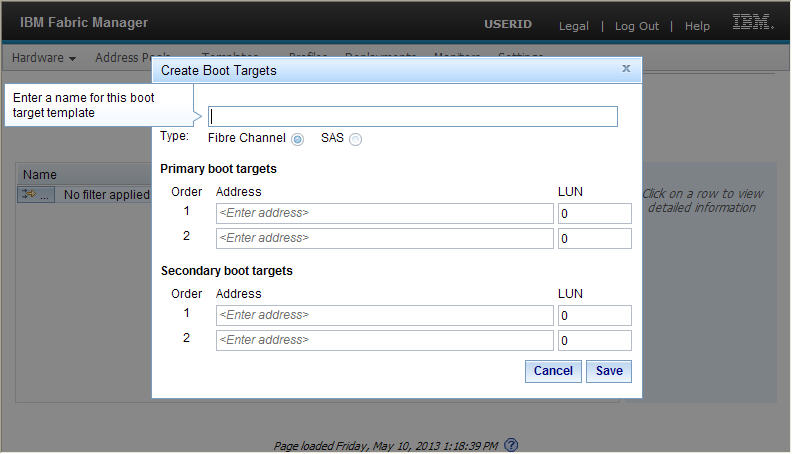
Boot Target
Select this choice to add, edit, or remove the default primary and secondary boot target information. A single template can be applied to multiple profiles.
-
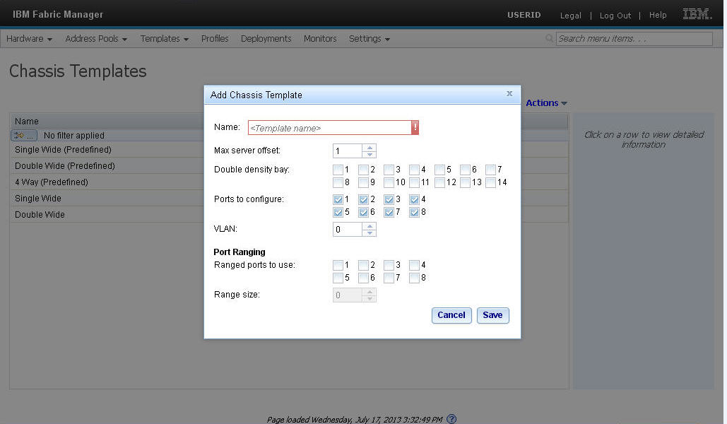
Chassis
Select this choice to add, edit, or remove the default chassis information. A single template can be applied to multiple profiles.
Some Ethernet adapters can have a range of MAC addresses per port. The range is defined by specifying two MAC addresses per port: MAC A and MAC B. Enter a range size between 2 and 256. The default value is 16.
Max Server Offset is the maximum width of any server associated with the pool. This is a 0 indexed value. For single-bay servers this value is 0. For two-bay servers this value is 1.
VLAN is the generic VLAN address. This VLAN tag is used only by the UEFI for the PXE boot. You must apply OS VLAN tags at the OS level.
Use Double density bay to define the bays that contain two servers in one bay.
Use Ranged ports to use to define the bays that can accept a range of addresses.
Range size defines the range size of MAC addresses. Enter a range size between 2 and 256.
-
vNIC
Select this choice to add, edit, or remove the default layout and QOS settings for the virtual NIC ports. A single template can be applied to multiple profiles.
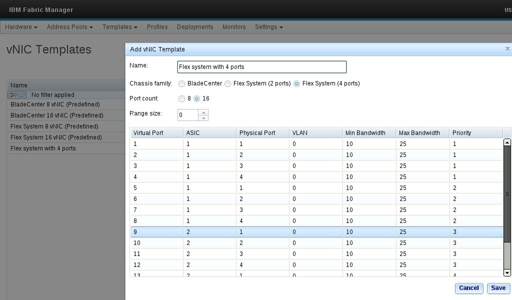
Min Bandwidth is the minimum bandwidth percentage associated with the virtual port. Minimum bandwidth must be smaller than the maximum bandwidth and must be at least 10. Max Bandwidth is the maximum bandwidth percentage associated with the virtual port. The total of the minimum bandwidth and maximum bandwidth must be 100.
To define virtual ports requiring a MAC B assignment, specify a range size greater than 0. When the deployment is generated, the vNIC entries will contain MAC B assignments for each of the virtual ports based on the range size.
Additionally, the port assignment order can be controlled by selecting BladeCenter, Flex System (2 ports), or Flex System (4 ports) which will use the predetermined order in which the virtual ports are assigned to the physical ports. You can use this feature to select the layout to support the installed network cards.
-
Boot Target