To add, delete, and manage hardware devices, complete the
following steps.
Before you begin
The following notes describe information that
you must consider when you add, delete, and manage hardware devices:
- The IP address can be any valid address in one of the following
formats:
- IPv4 dotted notation (for example, 192.168.0.1)
- IPv6 hexadecimal notation (for example, FE80::3BA7:94FF:FE07:CBD0)
- Human-readable Web addresses
- For larger installations, it is best practice to use human-readable
addresses only if the domain-name-server (DNS) is on the local network.
If the DNS is not local, the lookup time can slow the parsing substantially,
especially if there is an error and the name is not found.
Procedure
-
Select Hardware; then select Devices. The
summary view shows information about the hardware inventory. You can
also select a line to view detailed information.
License indicates if an enterprise activation
key is active for the chassis.
Source shows
the source of the data for programming ports on the network adapters.
See
Setting the out-of-band mode.
-
CMM: For IBM Flex System® devices, the information is from the CMM.
-
AMM: For IBM® BladeCenter® devices, the
information is from the AMM.
-
IFM: The virtualization data is from the IFM LDAP server.
To push deployments from bays that contain two servers, this value
must be IFM.
-
CP: (configuration patterns) The server was configured
externally.
-
Unknown: The mode definition failed.
-
Series of dots (...): Source information does not apply
to this device.
IFM Status shows the basic operating status of
the devices. To view detailed results for individual ports, click
the IFM Status field for the server. IFM Status is only
available when Power State is On and IFM Mode is Enabled.
Table 1. IFM status
| Power State |
IFM Mode |
IFM Status |
| Off |
Disabled |
Not available (N/A) |
| Off |
Enabled |
Not available (N/A) |
| On |
Disabled |
Not available (N/A) |
| On |
Enabled |
-
Normal: The server is operating normally.
-
Error: An error has occurred.
-
Pending: The IFM Status is updating.
|
-
Select an action from the following choices:
-
Toggle Power
Select this choice to toggle server power
on and off.
-
Toggle IFM Mode
Select this choice to change
the mode for an individual server. Mode toggles between Enabled and Disabled.
When you toggle Disabled, the system ignores all ports belonging
to the bay. The Disabled choice is available only when power
to the server is off.
-
Manual Failover
Select this choice to force
the failover process to start and transfer activity to a compatible
blade in a standby pool. For failover to occur to a standby server,
the standby server must be powered off, and IFM Mode set to Disabled.
To allow greater flexibility, some settings might be ignored when
finding a matching replacement standby server in the standby pool.
Unlike the failover monitor, this selection triggers the failover
without an inducing failover event.
-
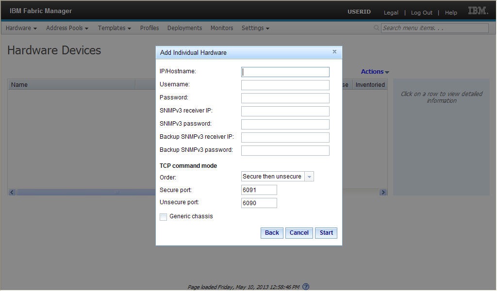
Add
Enter the userid and password
of the management modules to begin the Add action.
-
Add single chassis
Select this choice to add a chassis
from a single IP address. Click Generic chassis to add the
chassis to the database but not log in or gather inventory.
-
Add a range of chassis
Select this choice to add a chassis
from a range of IP addresses.
-
Add chassis from file or URL
Select this choice
to import IP addresses from a file or URL. A maximum of 100 IP addresses
can be imported and any additional IP addresses are ignored without
warning. The file must be a text file. You can enter only one valid
IPv4 or IPv6 address per line.
Enter the IP addresses or hostnames of the management
modules for hardware device discovery.
The following
information applies only when using SNMPv3 with IBM BladeCenter blade servers or IBM Flex System compute nodes.
Click Next to immediately log into the chassis
and gather inventory. For the TCP Command Mode, specify the discovery
order and the associated ports. A dialogue window opens and indicates
the progress of the discovery process.
-
Edit
Select this choice to edit the chassis credentials.
-
Remove
Select this choice to remove the chassis and
all associated servers from inventory.
-
Refresh
Select this choice to collect and refresh the
hardware inventory.