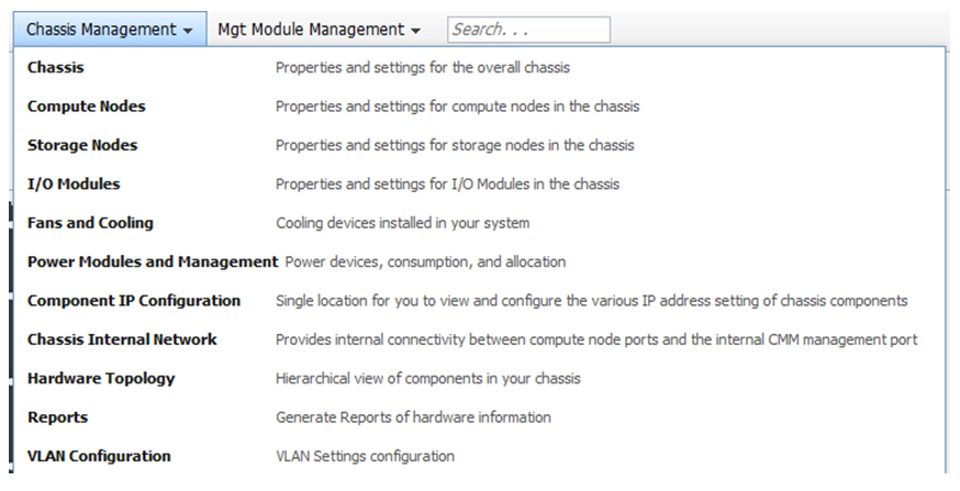
| Chassis Management |
Chassis |
Properties and settings for the overall chassis
can be accessed from the Chassis Management > Chassis page. The
following tabs are available on the Chassis:
|
| Chassis Management |
Compute Nodes |
The Compute Nodes page contains a table of the
compute nodes that are in the chassis. Each row has summary information
for an individual compute node, including name, type, health status,
power state, bay number, bay type, and machine type and model. You
can add more property columns by clicking Columns and selecting
more properties. Additional capabilities are provided through the
menus directly above the table. You can click the compute node name
to open a set of property tabs. You can access the compute node property
tabs from the System Status page, but with read-only permission. The
following options are available on the Compute Nodes page:
- Power and Restart - Contains options to perform power operations
on a specified compute node. The CMM web
interface generally updates the power status in real time, but some
operations might take longer. Check the event log for the results
of performing a power operation. Not all compute nodes support all
of the power options. The following options are available:
- Actions - Contains options that perform management functions on
the selected compute node. The following options are available:
- Launch Compute Node Console - Opens a compute node console in
a web session. Not all compute nodes support the ability to connect
through a web session.
- Identify LED - Options to turn on, off, or flash the blue LED
on the selected compute node to assist in locating the node in the
chassis.
- Global Settings - Contains options for the global configuration
of all compute nodes. The following options are available:
- Policies - Options to enable Wake on LAN and to enable the power
button on the selected compute node.
- Serial over LAN - Enable Serial over LAN (SOL) communication and
define SOL-specific transport parameters and keystroke sequences from
the Serial over LAN tab.
Note: You cannot update the firmware
for a compute node while the LAN over USB interface is disabled.
Before updating the firmware, you must re-enable the interface. After
updating the firmware, you can disable the interface again.
- Columns - Select the type of columns to display the compute node
information in.
- Detailed Properties - Click the compute node name to access the
following property tabs:
- Events - Contains a list of events for the selected compute node.
The entries are in the same format as the event log.
- General - Contains the following configuration options that are
specific to each compute node:
- Compute Node Name - Descriptive name assigned to the compute node.
If a name is not provided, the default name is the compute node serial
number preceded by the characters SN#.
(continued on the next page) |
| Chassis Management |
Compute Nodes |
(continued)
- Detailed Properties (continued)
(continued on the next page) |
| Chassis Management |
Compute Nodes |
- Detailed Properties (continued)
- General
- Powered On Time - Elapsed time since the selected compute node
has been powered on.
- Number of OS Boots - Number of times the node has booted from
the operating system since the most recent insertion into the chassis.
- Enable Serial Over LAN - Individual node setting for Serial over
LAN support.
- Enable Local Power Control - Individual node setting for the power
button on the node.
- Enable Ethernet Over USB - Individual node setting for the internal
Ethernet interface over USB. This field is not supported by all nodes
and is not visible when it is not supported.
Note: You cannot update
the firmware for a compute node while the Enable Ethernet Over
USB option is disabled. Before updating the firmware, you must
enable the option. After updating the firmware, you can disable the
option again.
- Hardware - Contains a hierarchical file tree on the left portion
of the screen and associated inventory data for the selected component.
A parent component (one with a +/- box) can be expanded to show its
associated child components. Click the parent component to view some
basic information about the parent component and a table of its associated
child components. The columns in the table provide full inventory
data of the associated child components. When the lowest level child
component is reached (one without a +/- box), click the node to view
full inventory data of the child component.
- Firmware - Identification information for the component firmware,
including installed network adapters. Some components might have multiple
firmware loads; in this case, the multiple firmware releases are contained
in a table.
- Power - Contains the following power statistics for the selected
component:
- Power State - Indicates whether the component is powered on or
off.
- Power In Use - Current power consumption of the component.
- Minimum/Maximum Allocation - Minimum and maximum power allocated
to the component.
- Capabilities - Power management capabilities that are supported
by the component.
- Power Saving Options - List of power saving policy settings. The
following settings are available:
- No power savings - Indicates that there is no power saving policy
set.
- Static low power saver - Reduces power consumption by altering
the operating voltage and frequency.
- Dynamic power saver - Controls the operating voltage and frequency
of the microprocessors, based on the load.
- Power Capping Options - Enables a power limit to control the maximum
power that is consumed by the component.
- Consumption History - Graphical representation of power consumption
over a set amount of time.
- Environmentals - Contains voltage and temperature information
for the selected component. Some components might provide one or more
threshold values.
(continued on the next page) |
| Chassis Management |
Compute Nodes |
- Detailed Properties (continued)
- IO Connectivity - Displays connectivity status and compatibility
details for the selected node and the I/O modules that it is connected
to.
- SOL Status - Contains information about Serial Over LAN connection
and configuration for the selected node.
- Boot Sequence - Contains options that enable the user to select
the order of boot devices for the node when it is powered on. The
options apply to compute nodes. Possible devices are displayed in
the order in which they will be powered on. The following attributes
are available for each device:
- Device ID - Numeric identifier of the device.
- Active - Whether the device can be used in the boot order.
- Presence - Whether the device is present. A missing device can
be added to the boot sequence. When the device is present, it will
be powered on.
- Device Label - Identification label provided by the device itself.
- User Label - Identification label specified by the user.
- Order - Location of the device in the boot order.
- LEDs - Displays LEDs that are present on the device, including
title, description, and state. All information viewed from the CMM graphical
view property tabs is read-only. You can access options to change
the state of some LEDs by clicking: Chassis Management > Compute
Nodes > Actions.
- Boot Mode - Contains boot options to indicate the location of
the active and pending compute node firmware. This tab applies only
to compute nodes and has the following options:
- Active boot mode - Location of the active copy of the compute
node firmware, either the temporary bank or the permanent bank.
- Pending boot mode - Location that the compute node firmware will
be obtained from on the next reboot, either the temporary bank or
the permanent bank.
|
| Chassis Management |
Storage Nodes |
The Storage Nodes page contains a table of the
storage nodes that are in the chassis. Each row has summary information
for the individual storage nodes, including device name, device type,
health status, power state, bay number, bay type, and machine type
and model. You can add more property columns by clicking Columns and
selecting more properties. Additional capabilities are provided through
the menus directly above the table. You can click the storage node
name to open a set of property tabs. You can access the storage node
property tabs from the System Status page, but with read-only permission.
The storage node name can be clicked to open the following tabs:
- Power and Restart - Contains options to perform power operations
on a specified compute node. The CMM web
interface generally updates the power status in real time, but some
operations might take longer. Check the event log for the results
of performing a power operation. Not all compute nodes support all
of the power options. The following options are available:
- Power On
- Power Off (SRC will shutdown the OS)
- Restart System Management Processor
(continued on the next page) |
| Chassis Management |
Storage Nodes |
(continued)
- Actions - Contains the following options that perform management
functions on the selected compute node:
- Launch Storage Node Console - Opens a storage node console in
a web session. Not all storage nodes support the ability to connect
through a web session.
- Identify LED - Options to turn on, off, or flash the blue LED
on the selected compute node to assist in locating the node in the
chassis.
- Detailed Properties - Click the compute node name to access the
property tabs. The following list includes all of the detailed properties,
but not every property applies to every component:
- Events - Contains a list of events for the selected node. The
entries are in the same format as the event log.
- General - Contains the following configuration options that are
specific to each storage node:
- Node Name - Descriptive name assigned to the compute node. If
a name is not provided, the default name will be the compute node
serial number preceded by the characters SN#.
- Auto Power On Mode - Storage nodes are automatically
powered on. This setting can not be configured for storage nodes.
- Power On Delay - Number of seconds a compute node power on action
is delayed. This gives the user control to power on the nodes process
of compute nodes in order to lower the traffic load on the management
bus.
- Node Bay Data - Customizable data that is stored on the node,
but is associated with the chassis bay that is occupied by the node.
When the node is inserted into a different bay, the previous node
bay data stored in the node is overwritten with the new node bay data.
Node bay data enables the node OS to read bay-specific data and configure
the node for the bay. You can enter up to 60 alphanumeric characters
for Node Bay Data.
- Bay Data Status - Storage nodes do not support bay
data status reporting.
- Hardware - Contains a hierarchical file tree on the left portion
of the screen and associated inventory data for the selected component.
A parent component (one with a +/- box) can be expanded to show its
associated child component. Click the parent component to view some
basic information about the parent component and a table of its associated
child components. The columns in the table provide full inventory
data of the associated child components. When the lowest level child
component is reached (one without a +/- box), click the node to view
full inventory data of the child component.
- Firmware - Contains identification information for the firmware
of the selected component, including installed network adapter cards.
If the selected component has multiple firmware loads, they will be
contained in a table.
(continued on the next page) |
| Chassis Management |
Storage Nodes |
- Detailed Properties (continued)
- Power - Contains power statistics for the selected component.
The power statistics include the following:
- Power State - Indicates whether the component is powered on or
off.
- Consumption - Current power consumption of the component.
- Allocation - Minimum and maximum power allocated for the selected
component.
- Capabilities - List of power management capabilities supported
by the selected node and statistics used in the power management algorithms.
- Power Saving Options - Storage nodes do not support
power saving options.
- Power Capping Options - Enables a power limit to control the maximum
power that is consumed by the component.
- Consumption History - Graphical representation of power consumption
over a set amount of time.
- Environmentals - Contains voltage and temperature information
for the selected component. Some components might provide one or more
threshold values.
- IO Connectivity - Contains information about the internal connectivity
status between I/O modules and the network adapter on the selected
storage node.
- LEDs - Contains information about LEDs that are present on the
selected component, including title, description and state of the
LED. Any LEDs that are capable of having their state changed are displayed
in the State column.
|
| Chassis Management |
I/O Modules |
The I/O Modules page contains a
table of the I/O modules that are in the chassis , with summary information
about each one, including device name string, health status, bay number,
power state, inventory information, and I/O compatibility details.
Additional capabilities are provided by menus located above the table.
You can also click the I/O module name to open property tabs.
- Power and Restart - Contains power operations for the
selected I/O modules. The web interface updates the power status in
real time, but some operations might take longer. Check the event
log for the results of a power operation. The following power options
are available are from the Power and Restart menu:
- Power On
- Power Off
- Restart Immediately and Run Standard Diagnostics
- Restart Immediately and Run Full Diagnostics
- Restart Immediately and Run Extended Diagnostics
- Actions - Contains the following menu options for the selected
module:
- Reset Factory Defaults - Sets the configuration to the factory
defaults
- Send Ping Requests - Sends a diagnostic stream of pings to the
module
- Launch IOM Console - Launches a web session to directly access
the module
- Identify LED - Manages the identification LED
- Detailed Properties - Click the I/O module name to access its
detailed properties. The following list includes all of the detailed
properties, but not every property applies to every component:
- Events - Contains a list of events that are relevant to the selected
component. The entries are in the same format as the full event log.
- General - Contains the following configuration options that are
specific to each I/O module:
- Stacking Mode - The current stacking mode state of the I/O module:
- N/A - The I/O module does not have stacking capability.
- Standby - The I/O module has stacking capability but is not part
of a stack at the moment.
- Master - The I/O module has stacking capability and is part of
a stack right now in the master role.
- Member - The I/O module has stacking capability and is part of
a stack right now in the member role.
- Post Status - The results of an I/O module power-on self-test
during switch initialization.
- Protected Mode Status - The current protected mode state of the
I/O module:
- N/A - Protected mode capability does not exist on the I/O module.
- Disabled - Protected mode capability exists on the I/O module,
but has not been enabled.
- Pending - Protected mode has been activated on the CMM, but is
still being activated for the I/O module.
- Active - Protected mode is active on the I/O module and the CMM.
- Attention - Protected mode is enabled on the I/O module,
but not on the CMM.
- Management Network Status - The internal management
network interface status for this I/O module. This field might not
be available for I/O modules that are members of a stack.
(continued on the next page) |
| Chassis Management |
I/O Modules |
- Detailed Properties (continued)
- General
- Internal Mgmt Port MAC - The internal management network
interface MAC address for this I/O module. This field might not be
available for I/O modules that are members of a stack.
- Power On Delay - Number of seconds an I/O module power on action
is delayed. Enables the ability for the user to stagger the powering
on of multiple I/O modules. This helps lower the traffic load on the
management bus.
- Enable data (non-management) ports - Enable or disable
the external ports of an I/O module. When the external ports are disabled,
no traffic can go through these ports. This setting can not be changed
when protected mode is enabled for the selected I/O module.
- Enable external management over all ports - Enable or disable
external configuration management of the selected I/O module. When
this field is set to disabled, only the management module ports
can be used to change the configuration on this module. When the field
is set to enabled, all ports, including internal, external,
and management module ports, can be used for configuration. This setting
cannot be changed when protected mode is enabled for the selected
I/O module.
- Preserve new IP configuration on all resets - Specifies if the
user-defined IP configuration will be saved. If this field is set
to enabled, be sure that a valid static IP configuration is
set for the selected I/O module so that when the defaults are restored,
or a reset is initiated by a source other than the CMM,
the static IP configuration will maintain communication between the CMM and
the selected I/O module. If this field is set to disabled,
the default IP configuration is active when the I/O module is reset
to defaults by the CMM or
the selected I/O module itself. If an I/O module reset is initiated
by a source other than the CMM,
the previous IP configuration is used and the CMM will
lose IP communications with the selected I/O module.
- Enable protected mode - Enables the protected mode function on
the CMM.
- Hardware - Contains a hierarchical file tree on the left portion
of the screen and associated inventory data for the selected component.
A parent component (one with a +/- box) can be expanded to show its
associated child components. Click a parent component to view some
basic information about the parent component and a table of its associated
child components. The columns in the table provide full inventory
data of the associated child components. When the lowest level child
component is reached (one without a +/- box), click the node to view
full inventory data of the child component.
- Firmware - Contains identification information for the
firmware of the selected component, including installed network adapters.
If the selected component has multiple firmware loads, they are contained
in a table. An inactive firmware version can be activated by selecting
the row, then clicking Make Active. To update a particular firmware
version, select the row and click Update. A firmware update wizard
will guide you through the options for updating your firmware, including
a direct update to the I/O module through an external server or a
local file update from the web client.
- Power - Contains the following power statistics for the selected
component:
- Power State - Whether the component is powered on or off.
- Power In Use - Current power consumption of the component.
(continued on the next page) |
| Chassis Management |
I/O Modules |
- Detailed Properties (continued)
- Power
- Maximum Allocated Power - Maximum power allowed for the selected
component.
- Consumption History - Graphical representation of power consumption
over a set amount of time.
- IO Connectivity - Connectivity status and compatibility details
for the selected I/O module and compute nodes that it is connected
to.
- Port Info - Contains detailed information about each
IO module port. Clicking the Full Port Info button provides additional
information as noted in some options that follow. The Full Port Info
might take several minutes to display. The following information is
shown on the Port Info tab:
- Port - Numeric value of the port number
- Label - Description of the port, which can be clicked to view
additional information such as cable length, cable vendor, cable compatibility,
and cable type.
- Port Type - Type of port, for example, internal or external.
- Protocol - Protocol used for the port, such as Ethernet or Fibre
Channel.
- Data Rate - Data rate used by the port, such as SDR,
DDR or QDR. This information is displayed after clicking Full Port
Info.
- Width - Numeric value of the port width. This information
is displayed after clicking Full Port Info.
- Media - Port media that is used, such as copper or fiber.
This information is displayed after clicking Full Port Info.
- Link Setting - Configurable link setting of the port.
- Speed Setting - Configurable speed setting of the port.
- Mode - Configurable duplex mode of the port.
- LEDs - Contains information about LEDs that are present on the
selected IO module, including title, description and state of the
LED. Any LEDs that are capable of having their state changed are displayed
in a list in the State column.
|
| Chassis Management |
Fans and Cooling |
The Fans and Cooling page provides detailed
information for all of the chassis fans and cooling devices. The following
property tabs are available:
- Cooling Devices - Fan modules and cooling devices with their properties,
including speed, zone association, fan status, and fan controller
status. Click the fan module name in the Fan column to access the
following properties:
- Events - Events that have occurred for the selected fan module.
- Power - Power consumption of the selected fan module.
- Cooling Zones - Status of each of the cooling zones in the chassis.
Click the zone name in the Zone column to access the following property
tabs:
- Fans - Summary information for the fan modules in the selected
cooling zone, including speed, fan status, and fan controller status.
- Components - Chassis components associated with the selected cooling
zone.
- Acoustic Attenuation - Enables the user to set a policy for how
quickly the chassis fan speed is increased in the case of a thermal
event on the selected node. When the option is set to Off,
the fan speed will increase without concern for acoustic noise limits.
A numeric value of 5 indicates the highest priority for remaining
within acoustic noise limits by limiting the amount the fan speed
can be increased. As a result, this setting increases the possibility
that the node might have to be throttled to remain within the acoustic
noise limit. As the setting number increases, less priority is placed
on remaining within acoustic noise limits.
|
| Chassis Management |
Power Modules and Management |
The Power Modules and Management page contains
power management policies and power hardware information. The following
tabs are available:
- Policies - Contains options to configure power policies for power
redundancy, in case of power module failure, and power limiting. The
following policies are available on the Policies tab:
- Power Redundancy Policy - Options to configure a backup power
source for the chassis. The following options are available:
- Power Source Redundancy - This option is intended for
dual power supplies in the chassis. Maximum input power is limited
to the capacity of half the number of installed power modules. This
is the most conservative approach and is recommended when all power
modules are installed. When the chassis is wired with redundant power
sources, one power source can fail without affecting compute node
operation. Some compute nodes might not be allowed to power on if
doing so would exceed the policy power limit.
- Power Source Redundancy with Compute Node Throttling
Allowed - This option is similar to the Power Source Redundancy policy;
however, this policy allows higher input power, however capable compute
nodes might be allowed to throttle down if one power source fails.
- Power Module Redundancy - Intended for a single power source in
the chassis where each power module has its own dedicated circuit.
The maximum input power is limited to the power of one less than the
total number of power modules when more than one power module is present.
One power module can fail without affecting compute node operation.
Multiple power module failures can cause the chassis to power off.
Some compute nodes might not be allowed to power on if doing so would
exceed the policy power limit.
- Power Module Redundancy with Compute Nodes Throttling Allowed
- This option enables higher input power, similar to the Power Module
Redundancy option. Some compute nodes might be able to throttle down
if a power module fails.
- Basic Power Management - The maximum input power is
higher than the other policies and is limited only by the indicated
power of all the power modules combined. This is the least conservative
option, with no protection for power source or power module failure.
When a power supply fails, compute node or chassis operation might
be affected.
- Power Limiting/Capping Policy - Policies for limiting the total
amount of power that the chassis is allowed to consume overall.
- No Power Limiting - Maximum input power is determined by the active
Power Redundancy Policy.
- Static Power Limiting - Sets an overall chassis limit on the maximum
input power. In a situation where powering on a component will cause
the limit to be exceeded, the component will not be permitted to power
on.
- Hardware - The Hardware tab provides the following options
to monitor the overall chassis power status and individual power module
information:
- Total DC Power Available - All of the power that is available
for the chassis.
- Power Modules - Table of installed power modules with the rated
power, status, and status details information of each.
- Power Modules Cooling - Table of installed power module cooling
modules with fan count, percent of average speed, average speed, and
fan controller state properties.
(continued on the next page) |
| Chassis Management |
Power Modules and Management |
(continued)
- Input Power and Allocation - The Input Power and Allocation
tab provides chassis power allocation information, a power consumption
graph, and a table containing each installed components power data.
The following property tabs are available:
- Overall - Contains the following information in a graphical pie-chart
format:
- Total Thermal Output - Output value in BTU per hour.
- Power Allocation - The following properties are available regarding
power allocation:
- Allocated - Maximum amount that all components together can theoretically
consume. The CMM maintains
at least this amount of power for chassis consumption.
- Remaining - Amount of power that remains for additional devices
- Current Power Consumption - Amount of power that is
currently being consumed.
- Average Input Power - Current average power consumption of all
components in the chassis.
- Remaining - Amount of power remaining for additional components.
- Details - Contains a table with the following information for
installed chassis components:
- Device Type - Description of the component.
- Device Name - Name assigned to the component.
- Bay - Chassis bay that the component occupies.
- Bay Type - Type of chassis baby that the component occupies.
- Power State - Current power state of the component.
- Average Input Power - Average power consumption.
- Minimum Allocated Power - Lower limit of allocated power for the
component.
- Maximum Allocated Power - Upper limit of allocated power for the
component.
- Power History - Chart of the power consumption history for this
chassis. The range of the vertical axis corresponds to the maximum
power, in watts, that is allocated for the chassis.
(continued on the next page) |
| Chassis Management |
Power Modules and Management |
(continued)
|
| Chassis Management |
Component IP Configuration |
The Component IP Configuration page allows the
user to configure and view IPv4 and IPv6 configuration settings for
compute nodes and I/O modules. The following sections are available:
- I/O Modules - Contains a table for each component type indicating
the location and description of the device, along with a viewable
list of active IP addresses. IPv6 support is required. IPv4 can be
disabled if necessary. Click the device name in the Device Name column
to access property tabs for the I/O module management interface. The
following property tabs are available:
- General Setting - Lists the MAC address of the I/O module
management interface. If an I/O module is a member of a stack, the
MAC address might not be displayed.
- IPv4 - Contains the following IPv4 properties:
- Configuration method - Static, DHCP, or DHCP with static fallback.
- Static IP address, mask, and gateway.
- IPv6 - Contains the following IPv6 properties:
- Link local address.
- Enable or disable DHCPv6 support.
- Enable or disable stateless auto-configuration.
- Enable or disable static IP support.
- Compute Nodes - Click the compute node name in the Device Name
column to access property tabs for the compute node. The following
property tabs are available:
- General Setting - Lists the MAC addresses of the compute node
management interfaces to the primary and standby CMM.
- IPv4 - Contains the following IPv4 properties:
- Configuration method - Static, DHCP or DHCP with static fallback.
- Static IP address, mask and gateway.
- IPv6 - Contains the following IPv6 properties:
- Link local address
- Enable or disable DHCPv6 support
- Enable or disable stateless auto-configuration
- Enable or disable static IP support
- IPv6 Auto-Config - When DHCPv6 or stateless auto-configuration
is enabled, the IPv6 Auto-Config tab is displayed. This tab
provides the following properties:
- DHCPv6 assigned addresses
- Stateless auto-configuration assigned IP addresses and prefix
lengths
- Storage Nodes - Click the storage node name in the Device Name
column to access property tabs for the node. The following property
tabs are available:
- General Setting - Lists the MAC addresses of the storage node
management interfaces to the primary and standby CMM.
- IPv4 - Contains the following IPv4 properties:
- Configuration method - Static, DHCP or DHCP with static fallback.
- Static IP address, mask and gateway.
(continued on the next page) |
| Chassis Management |
Component IP Configuration |
- Storage Nodes (continued)
- IPv6 - Contains the following IPv6 properties:
- Link local address
- Enable or disable DHCPv6 support
- Enable or disable stateless auto-configuration
- Enable or disable static IP support
- IPv6 Auto-Config - When DHCPv6 or stateless auto-configuration
is enabled, the IPv6 Auto-Config tab is displayed. This tab
provides the following properties:
- DHCPv6 assigned addresses
- Stateless auto-configuration assigned IP addresses and prefix
lengths
|
| Chassis Management |
Chassis Internal Network |
The Chassis Internal Network (CIN) provides
internal connectivity between compute node ports and the internal
management module management port. This capability allows a user to
access the CMM from
a compute node, for example, by opening a web, CLI, or SNMP session.
The communication path is two-way, so that the CMM can
also use services on the compute node, such as, LDAP, SMTP, DNS, and
NTP. The Chassis Internal Network page enables the user to monitor
the status of CIN sessions and change CIN parameters. The following
tabs are available:
- General - Contains the options to enable or disable the CIN function
globally. One of the following check boxes is available, depending
on the CIN current state:
- Enable Chassis Internal Network - Activates the CIN
- Management module reads the CIN entries
- When an entry is enabled and the CIN VLAN ID is new and does not
have a CIN interface, a new CIN interface based on that CIN VLAN ID
is created. Use the CIN IP address from the entry to create a host
route.
- When an entry is enabled and the CIN IP address is 0.0.0.0, start
ARP monitoring.
- Disable Chassis Internal Network - Deactivates the CIN
- Stops all ARP monitoring
- Deletes all host routes
- Deletes all CIN interfaces
- Status - Contains a summary list of all CIN sessions in a table.
The following properties are available for the list of CIN sessions:
- CIN VLAN ID - Virtual LAN (VLAN) ID supporting CIN
- CIN IP Address - IP address communicating on the CIN. An asterisk
(*) after the address indicates that the address was dynamically created
and not configured by the user.
- CIN MAC - MAC address associated with the IP address.
- Status - CIN connection status:
- Operational - CMM can
ping the CIN IP address.
- Not Operational - The CMM cannot
ping the CIN IP address. Verify that the compute node and the I/O
module are configured properly and the configurations are compatible
with those of the CMM.
- Disabled - CIN configuration was disabled by a CMM administrator.
- Configuration - Contains a table of CIN entries that allows you
to define, enable, disable, or delete CIN entries. A maximum of 14
CIN configuration entries are supported. The table columns are as
follows:
- Bay - Index between 1 and 14 (inclusive) to identify the CIN configuration.
- CIN VLAN ID - Virtual LAN (VLAN) ID that supports CIN. Values
can range from 3 to 4094 (inclusive). These VLAN IDs cannot be the
same as the one used for Serial over LAN.
(continued on the next page) |
| Chassis Management |
Chassis Internal Network |
- Configuration (continued)
- CIN IP Address - IP address that is allowed to communicate on
the CIN. The value of 0.0.0.0 indicates that any IP address can communicate
on the CIN. In this case, the CMM listens
on the CIN VLAN ID and learns the IP addresses dynamically. If you
want to restrict the addresses, you must define each IP address specifically.
CIN entries cannot have matching IP addresses, with the exception
of 0.0.0.0. Multiple CIN entries with an IP address of 0.0.0.0 are
allowed, provided that the VLAN IDs are different. The IP address
of a CIN entry cannot be multicast or match the CMM IP
address. If the CIN IP address is 0.0.0.0, the compute node IP address
for the CIN that is configured in the compute node operating system
cannot be in the same subnet as the CMM.
- Enable - Column that allows the user to enable, disable, or delete
a CIN configuration:
- Enabled - The CMM reads
the entry and creates a new CIN interface if the CIN VLAN ID is new
and does not have a CIN interface, and then adds a host route and
monitors communication path. ARP monitoring is started if the IP is
set to 0.0.0.0.
- Disabled - The host route is deleted. If this is the last IP address
that uses the CIN interface, ARP monitoring is stopped if the IP is
0.0.0.0 and the CIN interface is deleted if there is no other entry
that depends on it.
|
| Hardware Topology |
The Chassis Hardware Topology page contains
a hierarchical view of the components in the chassis. The graphical
hardware topology tree is located on the left panel and displays components
that can be clicked to display all of the associated inventory data
in the right panel. A parent component displays a +/- box and can
be expanded to show its associated child components. Click the parent
component to view information about the component and a table of its
associated child components. The table contains inventory data for
each child component. When the lowest level child component is reached,
you can click on the child component to view its inventory data. |
| Reports |
You can generate hardware reports for all components
that have MAC addresses or unique identifiers from the Reports page.
The following tabs contain tables with information about each connected
component:
- MAC Addresses - Contains summary information for all installed
chassis devices that have MAC addresses.
- Unique IDs - Contains summary information for all installed chassis
devices that have unique identifiers, including Fibre Channel WWNs,
storage SAS IDs, and Infiniband GUIDs. The device type indicators:
W, S, or G, are added after the name value to identify the type of
device.
- Firmware Analysis - Contains the primary firmware levels
of installed nodes in the chassis. This information is grouped by
machine type/model and groups two or more nodes with the same type/model.
This information is intended to be used for determining which components
might need firmware upgrades.
- Component Firmware - Contains a listing of all installed
firmware for compute nodes, storage nodes, node network cards, and
switches.
- IP Addresses - Contains a listing of all IP address
information for compute nodes, storage nodes, and switches.
|
| |
VLAN Configuration |
- Global VLAN Settings - Contains the option to globally enable
VLAN support for the CMM eth0 network interface. Configuring and applying
configuration changes might make the CMM inaccessible, for example,
if there is a mismatch with the network environment. To prevent the
CMM from becoming inaccessible, a temporary or uncommitted configuration
is provided as a backup. Configuration changes made to VLAN parameters
will be temporary until the user accepts the changes. All uncommitted
changes can be committed by clicking Commit. If temporary changes
are not committed within the selected revert timeout, the last committed
configuration will be restored. This allows the user to access the
CMM if the temporary changes resulted in inaccessibility. The revert
timeout can be configured for 1-255 minutes. The revert timer is started
when a configuration update is saved. The last committed changes are
restored when the revert timer expires, if the user did not commit
the temporary configuration.
- CMM VLAN Configuration - Contains the option to configure, add,
remove, or restart a VLAN. A maximum of two VLAN entries can be configured
on the CMM. The first VLAN entry is referred as the default entry.
The default entry is always enabled and initially has the SOL feature
assigned to it. It is always configured with the IPv4 and IPv6 configuration
of the CMM external eth0 network interface.
- Actions
- Add New VLAN - This option is used to define the second VLAN entry,
using a unique name and VLAN ID. In addition, the VLAN state can be
enabled and disabled and VLAN tagging can also be managed. The VLAN
may be configured with unique IPv4 and IPv6 network parameters and
static routes can be associated with each protocol.
- Actions - Select the second VLAN entry and the Actions menu is
made available with options to delete or restart the VLAN.
- Delete VLAN - This option is used to delete the second VLAN entry.
- Features Assignment - Assigns the available features to a VLAN,
or removes the feature assignment.
|